
Rapid calibration radio telescope receiver and calibration method

A radio telescope and receiver technology, applied to electrical components, antennas, etc., can solve cumbersome and time-consuming problems, achieve the effects of improving accuracy, reducing nonlinear factors, and improving utilization efficiency

Pending Publication Date: 2019-06-14
YUNNAN UNIV
View PDF3 Cites 0 Cited by
  • Summary
  • Abstract
  • Description
  • Claims
  • Application Information

AI Technical Summary

Problems solved by technology

The traditional calibration method needs to replace the local oscillator and filter equipment frequently, and compensate the impact of different local oscillators, filters, and changes in physical quantities such as receiving area, temperature, and pitch angle through nonlinear models, which is a cumbersome and time-consuming process. the process of

Method used


Image

  • Rapid calibration radio telescope receiver and calibration method
  • Rapid calibration radio telescope receiver and calibration method
  • Rapid calibration radio telescope receiver and calibration method

Examples


Embodiment Construction

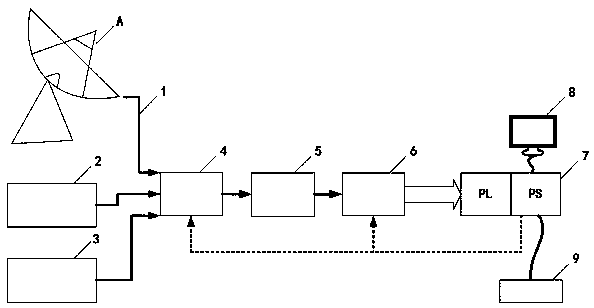
[0040] The fast calibration radio telescope receiver described in this embodiment is as follows: figure 2 As shown, it consists of a radio telescope radio frequency cable 1, a standard power white noise generator 2, a short circuit 3, a program-controlled radio frequency switch 4, a low noise amplifier 5, a radio frequency agile receiver 6 and an all-programmable system-on-chip 7; where the standard The power white noise generator 2 and the short circuiter 3 are respectively connected to the input end of the program-controlled radio frequency switch 4 through a radio frequency cable, and one end of the radio telescope radio frequency cable 1 is connected to the radio telescope, and the other end is connected to the input end of the program-controlled radio frequency switch 4, and the radio frequency The output end of the switch 4 is connected to the input end of the low noise amplifier 5 through a radio frequency cable, and the output end of the low noise amplifier 5 is connec...


PUM


Abstract

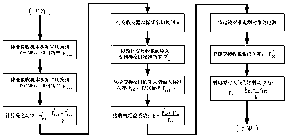
The invention relates to a fast and efficient radio telescope receiver and a fast calibration method based on the receiver. The local oscillator frequency of a radio frequency agile receiver is switched to bilaterally symmetrical frequency points f0+ / -deltaf with the observation center frequency f0 as the center with fully programmable system-on-chip software, and an average value of the output power is taken as the noise power P'sys of a system at the f0; the local oscillator frequency of the receiver is switched back to the f0, an input end of the receiver is short-circuited, the input is subjected to zero setting, and the output is used as the noise output power P'rec of the receiver; white noises with the power of Pcal are injected at the input end of the receiver, if the output powerof the receiver is P'cal, then the following formula is marked as a gain coefficient; and when the telescope and the radio frequency agile receiver are used for observing a radio source with the center frequency of f0, if the output power of the receiver is P'x, the input power of a calibrated radio telescope is as the following formula. The radio telescope receiver and the calibration method provided by the invention realize fast and accurate calibration and improve the utilization efficiency of the telescope.

Description

technical field [0001] The invention relates to a fast and efficient radio telescope receiver and a fast calibration method based on the receiver, belonging to the technical field of instruments and meters. technical background [0002] Collect and measure the radio signals emitted by celestial bodies (radio sources) through large radio telescopes, and then infer basic information such as the basic material composition and radiation excitation temperature of these radio sources, the velocity field in the movement area of ​​example density matter, and the magnetic induction intensity. important in physics research. The basis of the above research is the precise quantitative analysis of the spectrum of the radio signal obtained by the telescope. [0003] However, in actual measurement, different radio telescopes / receivers have different effective receiving areas, receiver sensitivities and noise levels, and the electromagnetic radiation intensity obtained when observing the s...

Claims


Application Information

Patent Timeline
IPC IPC(8): H01Q23/00H01Q19/12
Inventor 何乐生董亮谭景甲
Owner YUNNAN UNIV
Learn More