Flow heaters

a flow heater and heater technology, applied in the field of flow heaters, can solve the problems of limiting the efficiency with which water can be heated, overheating of heating elements, and significant drawbacks of technology, and achieve the effects of reducing heat loss, enhancing safety, and reducing the loss of hea

Inactive Publication Date: 2013-04-18
STRIX LTD
View PDF14 Cites 10 Cited by
  • Summary
  • Abstract
  • Description
  • Claims
  • Application Information

AI Technical Summary

Benefits of technology

[0021]In the first region, the controlled parameter is the water velocity (achieving a balance between good heat transfer with high velocity and acceptable hydraulic pressure drop) and in the second region the controlled parameter is water level, achieving a balance between heat transfer, by ensuring the heater is covered, and minimizing water volume by ensuring the water level is as low as possible. Minimizing water volume in the first and second regions maintains the fastest start-up time.
[0084]In some embodiments of the invention the steam path between the second region / final heating chamber and the atmosphere is sufficiently restricted to give rise to a pressure difference across it in use of between 0.1 and 1 bar, preferably between 0.2 bar and 0.5 bar. By allowing the second region / final heating chamber to become slightly pressurized in use as compared to the atmosphere, the boiling temperature of the water or other liquid is slightly increased which helps to raise the temperature of the liquid actually received in the user's receptacle.

Problems solved by technology

However such technology has significant drawbacks.
One of these is that there is a greater risk of the heating element overheating than with conventional batch heaters which limits the efficiency with which water can be heated.
As the bubbles rise they conduct heat to the cooler surrounding water and the resultant condensation eventually causes the bubble to collapse.
A pocket of steam will no longer provide cooling to the element surface.
The effect of this is rapid localized heating of the surface, and a failure, usually of the insulation between the heater track and heater substrate surface.
The Applicant has also appreciated that another problem arises with the use of a narrow water channel.
In addition to the undesirable effect of “spitting” from the users perspective, the depletion of water cover at the end sections of the heater can often lead to premature element failure.
The problems of localized hot spots and spitting place a constraint on the degree to which flow heater design can be optimized to maximize the ratio between the heater surface area and the volume of liquid which is needed to minimize heating times. Furthermore the need to provide adequate sensing of the element temperature to guard against overheating also compromises the heater design.

Method used


Image

  • Flow heaters
  • Flow heaters
  • Flow heaters

Examples


Embodiment Construction

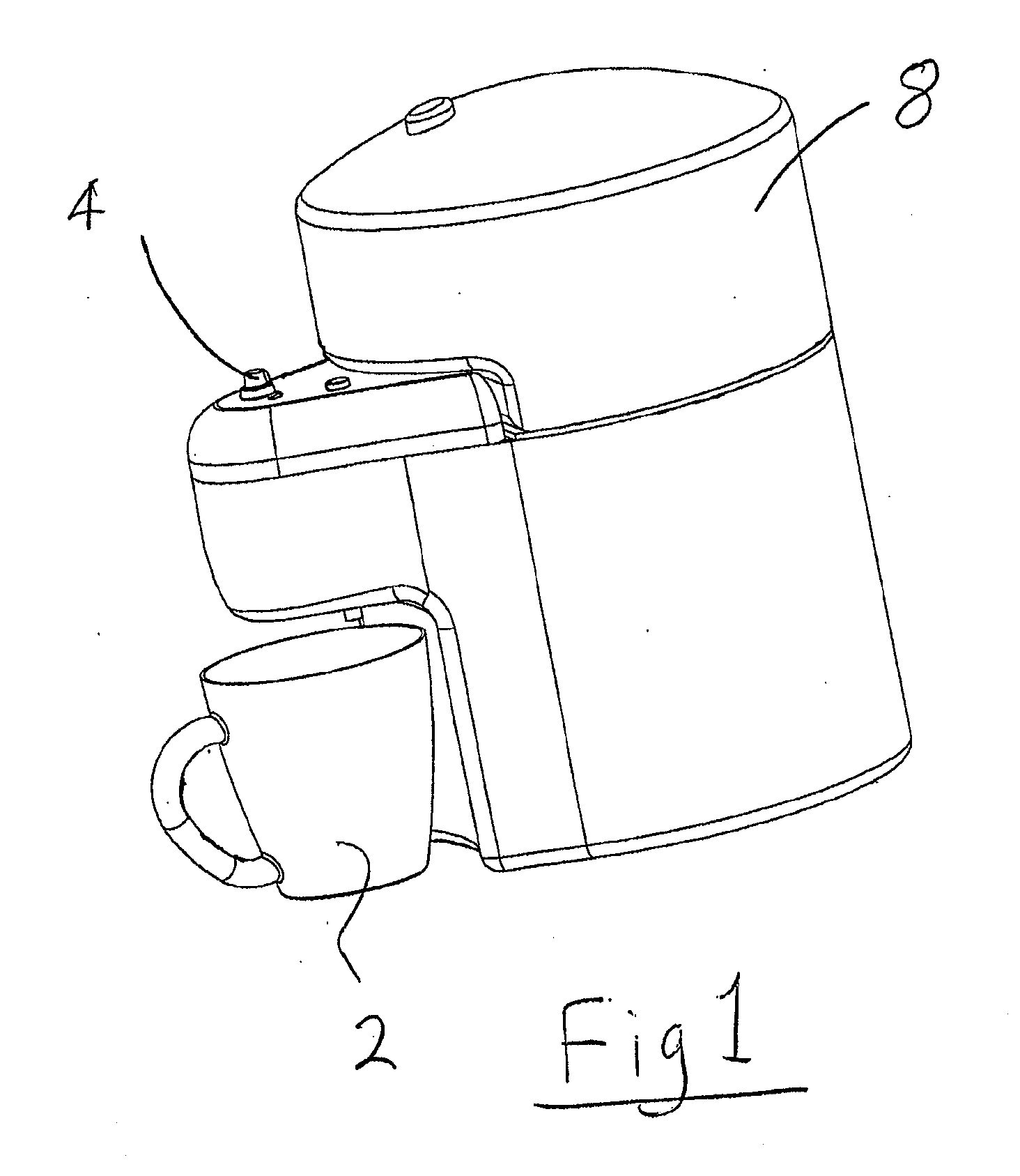
[0104]FIG. 1 shows an embodiment of the invention which can be used to dispense heated water, on demand into a cup 2 for making hot beverages. The temperature of the water can also be adjusted by turning a knob 4. The dispense temperature can be varied, for example, from 65° C. to nearly 100° C. The amount of water to be dispensed is controlled by a second knob (not shown). On the upper part of the main part of the apparatus is a water tank 8 which must be filled periodically by a user.

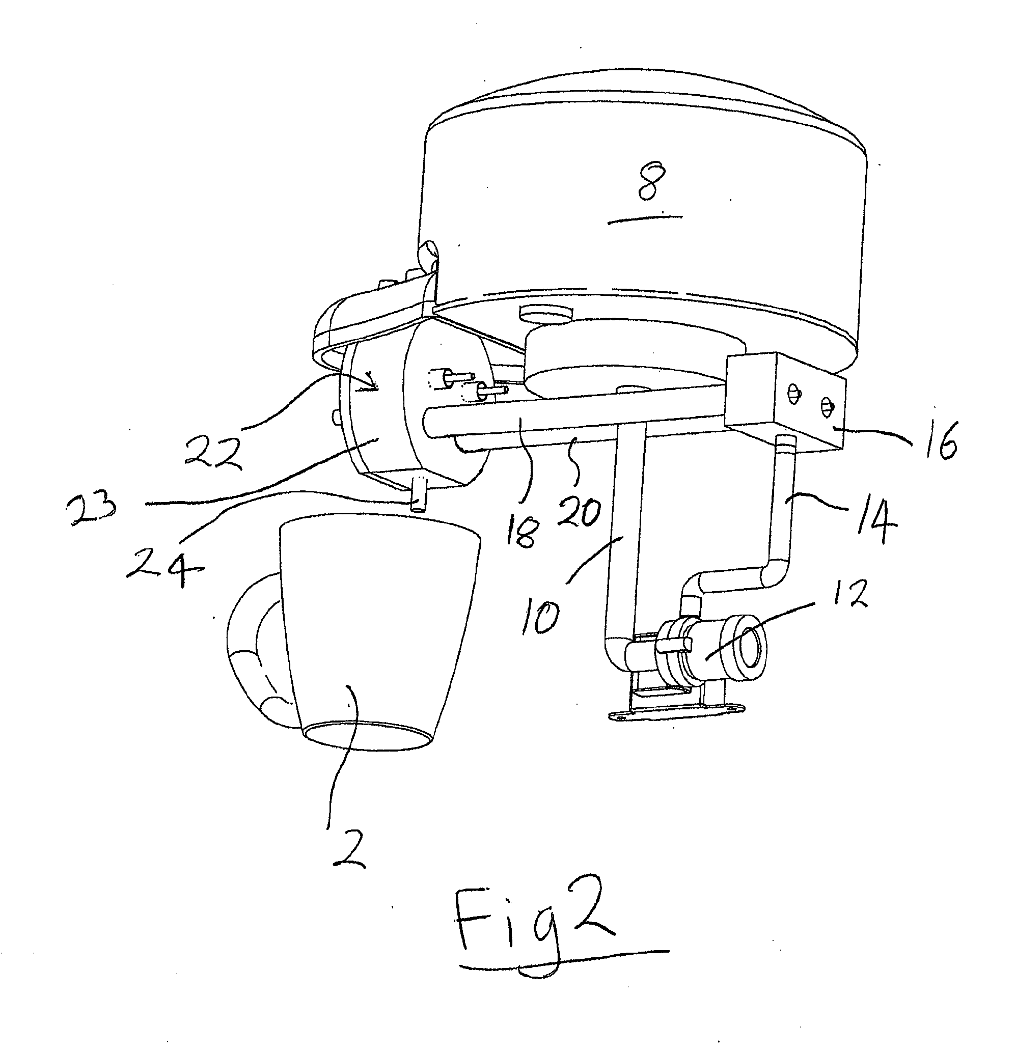
[0105]FIG. 2 shows some of the main internal components of the apparatus with other parts omitted for clarity. From here may be seen the water tank 8, extending downwardly from which is an outlet pipe 10 connected to the inlet side of a pump 12. The outlet side of the pump 12 is connected via a tube 14 to a water distribution plenum block 16 which distributes water entering the block between two parallel flow heater sections 18, 20 together forming a first heating region, as will be explained in great...


PUM


Abstract

A flow heater comprises a heating element (48; 248) and a first heating region (18, 20; 218, 220) heated by the heating element (48; 248) for heating liquid flowing therethrough to a first temperature below boiling. The flow heater also comprises a second heating region (22; 222) for heating the liquid to a second temperature below boiling. The second region (22; 222) has means (25; 225) for permitting the exit of steam therefrom separately from heated liquid. The flow heater cannot be operated so that bulk boiling of said liquid takes place in the second region (22; 222).

Description

[0001]This application is entitled to the benefit of, and incorporates by reference essential subject matter disclosed in PCT Application No. PCT / GB2010 / 052166 filed on Dec. 20, 2010, which claims priority to Great Britain Application No. 0922264.7 filed Dec. 21, 2009 and Great Britain Application No. 1015893.9 filed Sep. 22, 2010.BACKGROUND OF THE INVENTION[0002]1. Technical Field[0003]This invention relates to flow heaters for heating liquids, e.g. water.[0004]2. Background Information[0005]A number of methods are known to provide hot or boiling water for domestic consumption. Traditionally electric kettles or jugs are used to boil a quantity of water e.g. for making hot beverages.[0006]More recently products have been marketed which promise to deliver small quantities of hot water very quickly. Rather than heat a body of water in a batch, these are based on flow-heaters which heat water as it passes through a narrow passage with a thick film printed element on one side. However s...

Claims


Application Information

Patent Timeline
Patent Type & Authority Applications(United States)
IPC IPC(8): F24H1/00
CPCA47J31/542F24H1/0018F24H1/142A47J31/54F24H1/00F24H1/10
Inventor GARVEY, VINCENT JOSEPHGIBBS, NICHOLAS EDWARDMOUGHTON, COLINZHENG, YICAI
Owner STRIX LTD
Why Eureka
Try Eureka