Heaters

a technology of heat exchangers and heat exchangers, applied in the field of heat exchangers, can solve the problems of inability to boil water, bubbles to collapse, significant drawbacks in the technology, etc., and achieve the effects of accurate and stable determination of output temperature, accurate temperature measurement, and accurate and stable results

Active Publication Date: 2017-08-08
STRIX LTD
View PDF107 Cites 1 Cited by
  • Summary
  • Abstract
  • Description
  • Claims
  • Application Information

AI Technical Summary

Benefits of technology

[0019]In the first region, the controlled parameter is the water velocity (achieving a balance between good heat transfer with high velocity and acceptable hydraulic pressure drop) and in the second region the controlled parameter is water level, achieving a balance between heat transfer, by ensuring the heater is covered, and minimizing water volume by ensuring the water level is as low as possible. Minimizing water volume in the first and second regions maintains the fastest start-up time.
[0057]The Applicant has further appreciated that this arrangement allows even a relatively large heater surface to remain covered with a relatively thin covering of liquid and so avoid overheating.

Problems solved by technology

However such technology has significant drawbacks, the most important of which is that they cannot be used to boil water as is explained below.
As the bubbles rise they conduct heat to the cooler surrounding water and the resultant condensation eventually causes the bubble to collapse.
A pocket of steam will no longer provide cooling to the element surface.
The effect of this is rapid localized heating of the surface, and a failure, usually of the insulation between the heater track and heater substrate surface.
The Applicant has also appreciated that another problem arises with the use of a narrow water channel.
In addition to the undesirable effect of “spitting” from the users perspective, the depletion of water cover at the end sections of the heater can often lead to premature element failure.
The problems of localized hot spots and spitting means that flow heaters can't be used to provide boiling water.
In fact the hotter the water temperature aimed for, the greater these problems are.
In practice therefore, flow heaters have been restricted to applications requiring water at temperatures below boiling such as shower heaters, and hot water dispensers that do not boil water.

Method used


Image

  • Heaters
  • Heaters
  • Heaters

Examples


Embodiment Construction

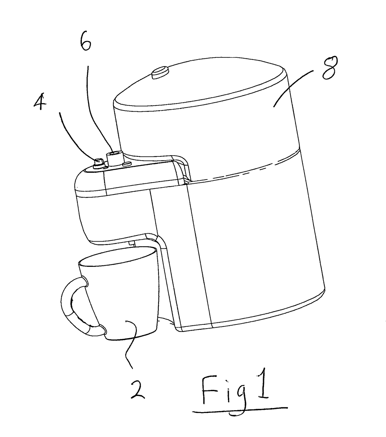
[0076]FIG. 1 shows an embodiment of the invention which can be used to dispense boiling water, on demand into a cup 2 for making hot beverages. The temperature of the water can also be adjusted by turning a knob 4. The dispense temperature can be varied from 65° C. to just boiling and beyond that to ‘rolling boil’ where more energy is put into the water to ensure that the whole volume is fully boiling. The amount of water to be dispensed is controlled by a second knob (not shown). Also visible is a steam outlet 6. On the upper part of the main part of the apparatus is a water tank 8 which must be filled periodically by a user.

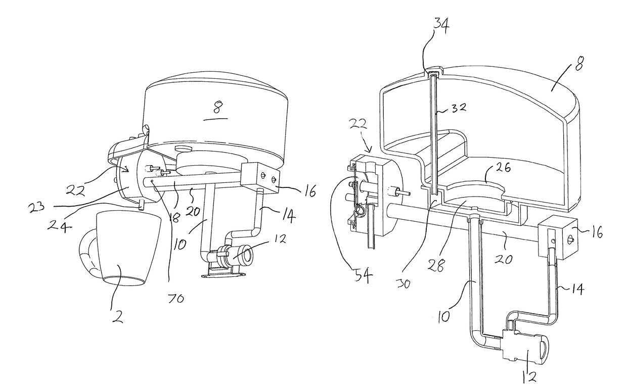
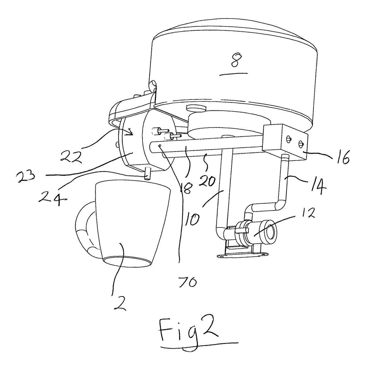
[0077]FIG. 2 shows some of the main internal components of the apparatus with other parts omitted for clarity. From here may be seen the water tank 8, extending downwardly from which is an outlet pipe 10 connected to the inlet side of a low voltage, centrifugal pump 12. The outlet side of the pump 12 is connected via a tube 14 to a water distribution plenum blo...


PUM


Abstract

A heater for heating liquid to boiling comprises a heating element (48; 106), a first heating region (18, 20; 100) heated by said heating element (48; 106) for heating liquid flowing therethrough to a temperature below boiling, and a second heating region (22; 102) for heating said liquid to boiling. The second region permits the exit of steam therefrom separately from heated water.

Description

[0001]This application is entitled to the benefit of, and incorporates by reference essential subject matter disclosed in PCT Application No. PCT / GB2010 / 001020 filed on May 20, 2010, which claims priority to Great Britain Application No. 0908718.0 filed May 20, 2009 and Great Britain Application No. 0922264.7 filed Dec. 21, 2009. This application is related to U.S. patent application Ser. No. 13 / 518,290 filed Dec. 4, 2012.BACKGROUND OF THE INVENTION[0002]1. Technical Field[0003]This invention relates to heaters for heating, particularly to boiling liquids, e.g. water.[0004]2. Background Information[0005]A number of methods are known to provide hot or boiling water for domestic consumption. Traditionally electric kettles or jugs are used to boil a quantity of water e.g. for making hot beverages.[0006]More recently products have been marketed which promise to deliver small quantities of hot water very quickly. Rather than heat a body of water uniformly, these are based on flow-heaters...

Claims


Application Information

Patent Timeline
Patent Type & Authority Patents(United States)
IPC IPC(8): A47J31/00F24H9/00F24H1/10H05B3/40A47J31/54F24H1/14F24H9/18F24H9/20H05B3/44
CPCA47J31/542F24H1/102F24H1/142F24H9/0015F24H9/1818F24H9/2028H05B3/44A47J31/54F24H1/10F24H15/246F24H15/219F24H15/132F24H15/174F24H15/238F24H15/355
Inventor GARVEY, VINCENT JOSEPHMOUGHTON, COLINZHENG, YICAI
Owner STRIX LTD
Why Eureka
Try Eureka