Optical accelerometer

An accelerometer and acceleration technology, applied in the field of inertial sensing technology and precision measurement, to achieve the effect of high sensitivity, high resolution, and avoiding mechanical coupling of motion

Active Publication Date: 2013-12-11
CHONGQING UNIV OF POSTS & TELECOMM
View PDF4 Cites 11 Cited by
  • Summary
  • Abstract
  • Description
  • Claims
  • Application Information

AI Technical Summary

Problems solved by technology

There are many literatures on optical accelerometers at home and abroad, and many methods for improving the measurement accuracy of light intensity modulated optical accelerometers have been proposed. The need for further research

Method used


Image

  • Optical accelerometer
  • Optical accelerometer
  • Optical accelerometer

Examples


Embodiment 1

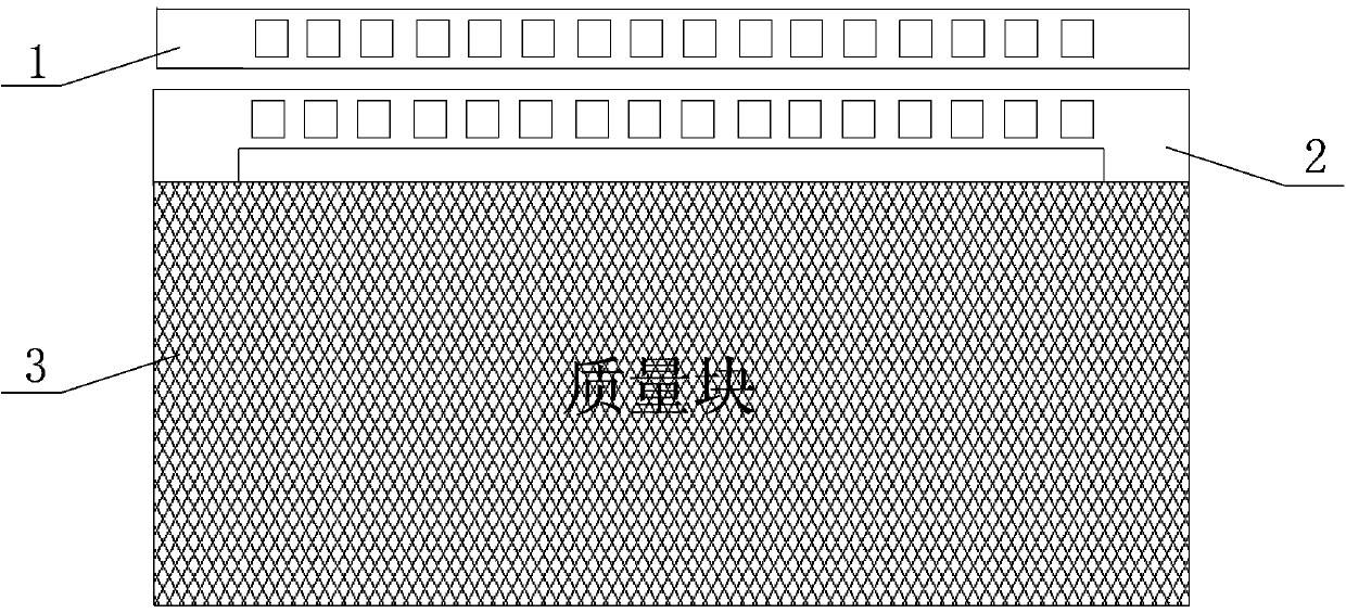
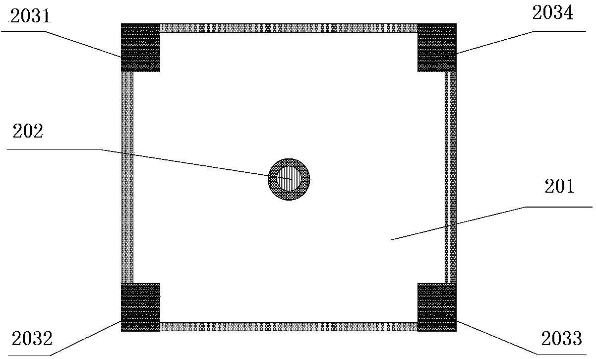
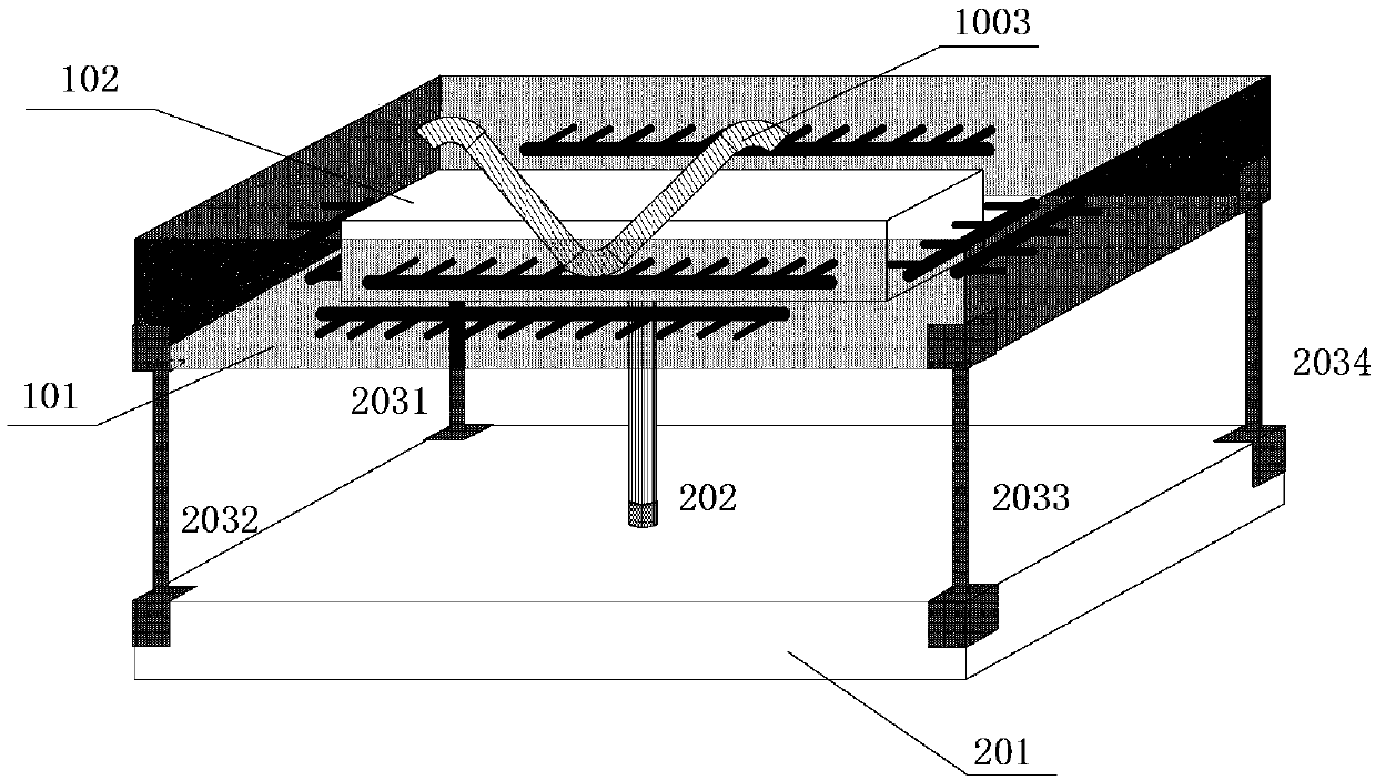
[0054] figure 1 It is a schematic diagram of the plane structure of the acceleration plane detection module in the XY axis direction, figure 2 A schematic diagram of the supporting module structure, image 3 It is a schematic diagram of the three-dimensional structure of a new multi-axis optical accelerometer, Figure 4 It is a schematic diagram of the photonic crystal cavity structure in the X-axis direction of the acceleration plane detection module in the XY-axis direction, Figure 5 It is a schematic diagram of the structure of the photonic crystal cavity in the Y-axis direction of the acceleration plane detection module in the XY-axis direction, Figure 6 It is a schematic diagram of a new multi-axis optical accelerometer detection module, as shown in the figure: the optical accelerometer provided by the present invention includes a detection module and a detection module; the detection module is used to convert the displacement change produced by the acceleration of t...

Embodiment 2

[0090] The difference between this embodiment and embodiment 1 is only:

[0091]The multi-axis optical accelerometer provided by the present invention includes a detection module and a detection module; wherein the detection module is composed of X and Y axis direction acceleration plane detection modules and a support module; wherein in the XY axis direction acceleration plane detection module, the first X axis can be The movable photonic crystal beam 1031 and the second X-axis movable photonic crystal beam 1033 are respectively fixed at the center position of the test mass 102YOZ plane surface and parallel to the Y-axis, for detecting the acceleration in the X-axis direction; the first Y-axis movable photonic crystal beam The beam 1032 and the second Y-axis movable photonic crystal beam 1034 are respectively fixed on the center position of the XOZ plane surface of the test mass 102 and parallel to the X-axis for acceleration detection in the Y-axis direction; the first X-axis...

Embodiment 3

[0103] The difference between this embodiment and embodiment 1 is only:

[0104] An implementation example of the present invention is described in detail below in conjunction with the accompanying drawings:

[0105] Such as image 3 As shown, a new type of multi-axis optical accelerometer consists of a detection module and a detection module. Among them such as figure 1 As shown, the detection module consists of a support frame 101, a test mass 102, a first X-axis movable photonic crystal beam 1031, a second X-axis movable photonic crystal beam 1033, a first Y-axis movable photonic crystal beam 1032, a second Y-axis movable photonic crystal beam 1034, first X-axis fixed photonic crystal beam 1041, second X-axis fixed photonic crystal beam 1043, first Y-axis fixed photonic crystal beam 1042, second Y-axis fixed photonic crystal beam 1044, support The mass block 201, the elastic beam 202, and the rigid beam of the support beam are composed of four, namely, the first rigid be...


PUM


Abstract

The invention discloses a novel multi-axis optical accelerometer which comprises a supporting structure, an elastic beam, a testing mass block, movable photonic crystal beams, fixed photonic crystal beams, connecting optical fibers, a variable optical attenuator, an optical fiber polarization controller, a balance optical detector and an electronic spectrum analyzer, wherein the testing mass block can respectively achieve acceleration signal detection on the X axis and the Y axis. Acceleration detection in the X axis direction and the Y axis direction is bidirectional acceleration detection only for the plane, and the detection is carried out by the testing mass block supported by a corresponding supporting structure. A corresponding detection edge of the testing mass block forms cavity-shaped structures by means of the silicon nitride photonic crystal beams manufactured through a micromachining process, and the crystal beam relative displacement changes produced by acceleration are converted into changes of detection optical signals. Photonic crystal cavities in different directions have no effect on acceleration signal detection in the directions. According to the optical accelerometer, the changes of the detection optical signals are converted into acceleration of a measurement carrier through a detection module, so the optical accelerator has the advantages of being high in measurement precision, resistant to electromagnetic interference, and the like.

Description

technical field [0001] The invention belongs to the technical fields of inertial sensing technology and precision measurement, and relates to a novel multi-axis optical accelerometer, in particular to a multi-axis photonic crystal cavity acceleration sensor which can be integrated on a chip. Background technique [0002] The accelerometer is a component that measures the linear acceleration of the carrier. It plays an important role in the fields of inertial navigation, inertial guidance and control testing equipment. It is currently widely used in aviation, navigation, vehicles, consumer electronics, medical treatment, weapon guidance and other fields. The field of accelerometers has experienced decades of development and has formed many types. Among them, the optical accelerometer has become a research hotspot of accelerometers at home and abroad in recent years because of its anti-electromagnetic interference, electrical insulation, and corrosion resistance. The developm...

Claims


Application Information

Patent Timeline
Patent Type & Authority Applications(China)
IPC IPC(8): G01P15/093
Inventor 刘宇刘聪刘期烈刘申方针吴英何晓艳陈燕苹王伊冰王乐江宏毅刘松
Owner CHONGQING UNIV OF POSTS & TELECOMM
Why Eureka
Try Eureka