

Head-wearing display equipment
A head-mounted display and equipment technology, applied in the direction of digital data authentication, etc., can solve the problems of limiting cost, size display area efficiency, etc., and achieve the effect of reliable interaction
- Summary
- Abstract
- Description
- Claims
- Application Information
AI Technical Summary
Problems solved by technology
Method used
Image

Examples
Embodiment Construction
[0021] Embodiments of the present invention are described in detail below with reference to the accompanying drawings. According to the number of display screens of the HMD, the HMD may be subdivided into a single-lens HMD and a dual-lens HMD. The present invention is applicable to both single-lens HMDs and dual-lens HMDs.
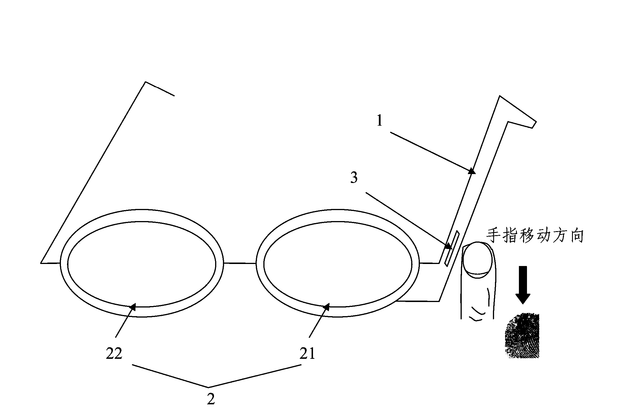
[0022] figure 1 is a schematic view showing a front view of a head-mounted display device according to an embodiment of the present invention.
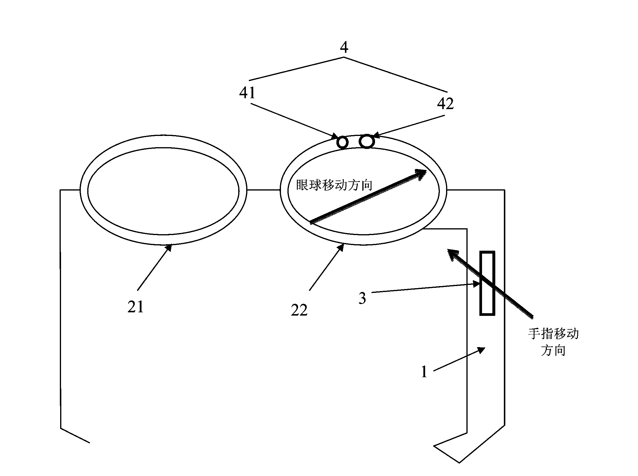
[0023] refer to figure 1 , the head-mounted display device may include a frame 1, a display screen 2, a biometric scanning unit 3 and an authentication interface unit (not shown).
[0024] The frame 1 can be made of specific materials (such as lightweight materials such as carbon fiber). The display screen 2 is installed in the frame 1 of the head-mounted display device. The display screen 2 may be provided with a touch control interface or a microphone in cooperation with a voice recognition module to receiv...
PUM
 Abstract
Description
Claims
Application Information