Cold cathode structure for magnetron and millimeter wave magnetron

A cold cathode and magnetron technology, applied to the cathode of the time-of-flight electron tube, etc., can solve the problems of inability to provide secondary electron emission, unsuitable application of magnetron, and evaporation of materials emitted by the cathode, so as to improve the control of fighters ability, strong resistance to electron return bombardment and ion bombardment, and large emission current

Pending Publication Date: 2017-07-25
NO 12 RES INST OF CETC
View PDF3 Cites 2 Cited by
  • Summary
  • Abstract
  • Description
  • Claims
  • Application Information

AI Technical Summary

Problems solved by technology

[0003] However, in the prior art, a hot cathode is generally used as the electron source of the magnetron, and the magnetron using this cathode has the following technical problems: first, the cathode must be preheated by a heater before work, and the preheating time At least 1 minute, sometimes even as high as 5 minutes; second, in order to preheat the hot cathode of the magnetron, the power supply of the magnetron must be added to the filament power supply part, and generally the filament transformer is floating on the negative high voltage of the cathode, the complexity of the power supply Third, the operating temperature of the hot cathode is generally above 850 ° C, the high operating temperature, the serious evaporation of the cathode emission material, and the low life
[0004] In the prior art, the carbon nanotube cold cathode adopts a planar emission structure, which is generally used for primary emission occasions. It has poor bombardment resistance and cannot provide secondary electron emission, so it is not suitable for application in magnetrons.
However, the cathode structure that provides secondary emission in the prior art is a composite cold cathode, and its secondary emitter is a tungsten sponge or a nickel sponge. It is also easy to precipitate gas under the bombardment of an electron. Generally, it is necessary to use a hot wire to degas the cathode at high temperature, which increases the complexity of the structure.

Method used


Image

  • Cold cathode structure for magnetron and millimeter wave magnetron
  • Cold cathode structure for magnetron and millimeter wave magnetron
  • Cold cathode structure for magnetron and millimeter wave magnetron

Examples


Embodiment 1

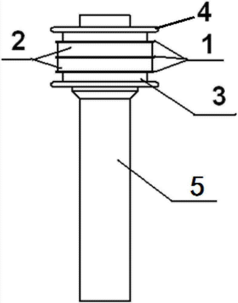
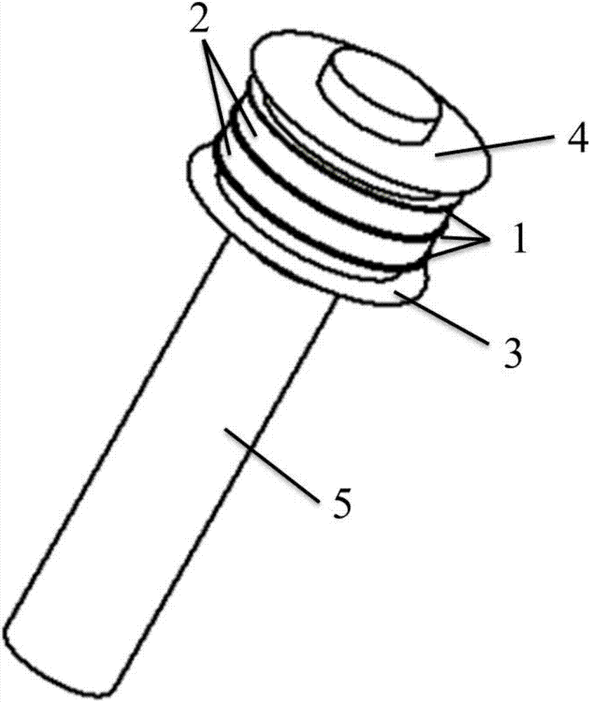
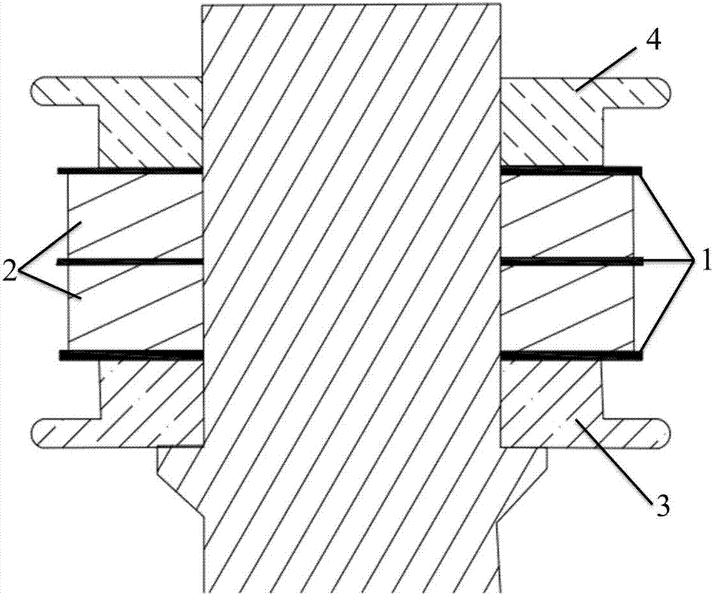
[0045] A cold cathode structure for millimeter wave magnetrons, such as Figure 1~3 As shown, it includes a bottom metal rod 5, an upper shield cap 4 and a lower shield cap 3 sheathed at one end of the bottom metal rod, and a cold cathode emitter arranged between the upper shield cap and the lower shield cap.

[0046] The cold cathode emitter includes three tantalum rings 1 and two palladium-barium rings 2. The tantalum rings and the palladium-barium rings are alternately arranged; the cold cathode emitter is shielded from the upper through the upper end surface of the top tantalum ring and the lower end surface of the bottom tantalum ring The cap 4 and the lower shield cap 3 are tightly connected.

[0047] The cold cathode emitter, the upper shielding cap and the lower shielding cap are all fixed on the bottom metal rod 4 by means of laser welding.

[0048] The bottom metal rod is a cylinder with a diameter of 2.8mm and a height of 20mm. The diameter of the tantalum ring 1 is 5.1 ...

Embodiment 2

[0051] The cold cathode structure of Example 1 is used to replace the hot cathode component in the hot cathode magnetron to obtain a new cold cathode magnetron.

[0052] The magnetron is tested, and the magnetron has normal vibration characteristics without obvious hysteresis. The vibration time is less than 5s, and the magnetron works stably. When high voltage (voltage waveform such as Figure 4 After A), the RF envelope is as Figure 4 As shown in middle B, this envelope is consistent with the normal envelope of a hot cathode magnetron, the pulse width reaches the normal pulse width of 400ns, and other electrical parameters are also normal.

[0053] In order to verify the vibration characteristics of this cold cathode, a cold cathode magnetron life test was carried out. The magnetron was cold-started 200 times. After 500 hours of normal operation, the magnetron cold-started normally, and all electrical parameters met the index requirements. Figure 5 It is the output power change c...

Embodiment 3

[0055] A cold cathode structure for a millimeter-wave magnetron is the same as Embodiment 1, except that the bottom metal rod is a cylinder with a diameter of 2.0 mm and a height of 15 mm. The diameter of the tantalum ring is 5.0mm and the thickness is 0.01mm. The diameter of the palladium barium ring is 5.0mm and the thickness is 1.5mm. The total thickness of the cold cathode emitter is 3.03 mm.

[0056] The cold cathode structure is used to replace the hot cathode component in the hot cathode magnetron, and a new cold cathode magnetron is obtained. The magnetron was tested, and the test results met the requirements.


PUM


Abstract

The invention discloses a cold cathode structure for a magnetron, comprising a bottom metal rod, an upper shielding cap and a lower shielding cap sheathed on one end of the bottom metal rod, and a cold cathode arranged between the upper shielding cap and the lower shielding cap The emitter, the cold cathode emitter includes alternately arranged primary emitters and secondary emitters, and the primary emitters are located at both ends of the cold cathode emitter. The invention also discloses a millimeter-wave magnetron with a cold cathode structure, wherein the thickness of the cold cathode emitter is 0.62-6.5mm. The invention realizes the reliable interaction between the primary electron and the secondary multiplication phenomenon by alternately setting the primary emitter and the secondary emitter, and ensures the reliable startup of the magnetron; the magnetron manufactured by the cold cathode structure of the present invention No need for filament heating, instant start-up, no obvious start-up lag time, and electrical parameter characteristics after start-up are consistent with those of hot cathode magnetrons.

Description

Technical field [0001] The invention relates to the technical field of microwave vacuum electronics. More specifically, it relates to a cold cathode structure for a magnetron and a millimeter wave magnetron. Background technique [0002] Magnetrons are the most widely used vacuum microwave tubes in military and civil fields. They have the advantages of simple structure, high pulse power, long life, high cost, and small size. They can be used in missiles, communications, beacons, warning radars, etc. In the military field, it can be widely used in civilian fields such as medical treatment, communication, meteorology, chemical industry, industrial heating, and automobile ignition. [0003] However, in the prior art, a hot cathode is generally used as the electron source of a magnetron. Magnetrons working with this cathode have the following technical problems: First, the cathode must be preheated with a thermon before operation, and the preheating time At least 1 minute, sometimes ...

Claims


Application Information

Patent Timeline
Patent Type & Authority Applications(China)
IPC IPC(8): H01J23/05
CPCH01J23/05
Inventor 黎深根李凤玲
Owner NO 12 RES INST OF CETC
Why Eureka
Try Eureka