head mounted display device

A head-mounted display and equipment technology, applied in the direction of digital data authentication, etc., can solve problems such as cost limitation, size display area efficiency, etc., and achieve reliable interaction effect

Active Publication Date: 2016-10-05
BAIDU ONLINE NETWORK TECH (BEIJIBG) CO LTD
View PDF10 Cites 1 Cited by
  • Summary
  • Abstract
  • Description
  • Claims
  • Application Information

AI Technical Summary

Problems solved by technology

However, these applications are currently limited by cost, size, display area, and efficiency issues of conventional optics used to implement current HMDs

Method used


Image

  • head mounted display device
  • head mounted display device
  • head mounted display device

Examples


Embodiment Construction

[0021] Embodiments of the present invention are described in detail below with reference to the accompanying drawings. According to the number of display screens of the HMD, the HMD may be subdivided into a single-lens HMD and a dual-lens HMD. The present invention is applicable to both single-lens HMDs and dual-lens HMDs.

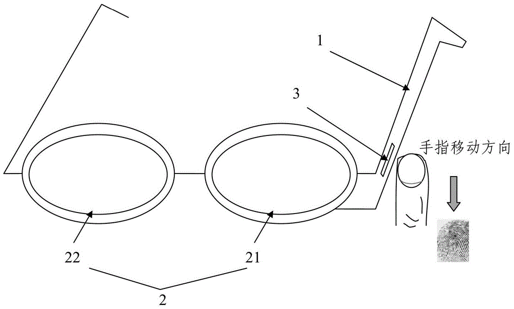
[0022] figure 1 is a schematic view showing a front view of a head-mounted display device according to an embodiment of the present invention.

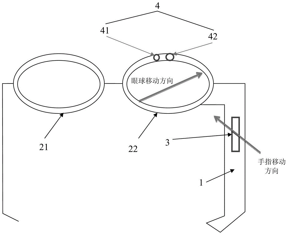
[0023] refer to figure 1 , the head-mounted display device may include a frame 1, a display screen 2, a biometric scanning unit 3 and an authentication interface unit (not shown).

[0024] The frame 1 can be made of specific materials (such as lightweight materials such as carbon fiber). The display screen 2 is installed in the frame 1 of the head-mounted display device. The display screen 2 may be provided with a touch control interface or a microphone in cooperation with a voice recognition module to receiv...


PUM


Abstract

The present invention provides a head-mounted display device. The head-mounted display device includes: a biological feature scanning unit that scans the biological features of the user wearing the head-mounted display device; an authentication interface unit that scans the biological features from the The unit receives the biometric scan result, and sends the biometric scan result to the remote server, so that the remote server can authenticate the user's biometric feature.

Description

technical field [0001] The present invention relates to the field of display, in particular to a head-mounted display device. Background technique [0002] A head mounted display device (Head Mounted Display, HMD) refers to a display device that can be worn on the head. HMDs generally use a "near-eye optical system" to display multimedia information such as graphics and pictures on a display screen (such as a lens) a few centimeters away from the eyeball. According to the number of display screens, HMDs can be subdivided into "single-lens HMDs" and "dual-lens HMDs". Some HMDs display only one "computer-generated image" (CGI), while some kinds of HMDs can display superimposed CGI in a "real-world perspective." The latter is generally referred to as "augmented reality" because the user's image information about the real world is "enhanced" by the image attached to the display device. Specifically, the user can not only watch the outside world around him through the transpar...

Claims


Application Information

Patent Timeline
Patent Type & Authority Patents(China)
IPC IPC(8): G06F21/32
Inventor 吴先超
Owner BAIDU ONLINE NETWORK TECH (BEIJIBG) CO LTD
Why Eureka
Try Eureka