Projector and control method for the projector

一种控制方法、投影仪的技术,应用在投影仪领域,能够解决投影系统不能够受理用户等问题,达到实现可用性的效果

Active Publication Date: 2013-12-18
SEIKO EPSON CORP
View PDF4 Cites 9 Cited by
  • Summary
  • Abstract
  • Description
  • Claims
  • Application Information

AI Technical Summary

Problems solved by technology

[0004] However, if the projector that received the command has some abnormality or the like and cannot perform normal operation, there is a problem that the projection system cannot operate in response to the user's operation even if other projectors operate normally.

Method used


Image

  • Projector and control method for the projector
  • Projector and control method for the projector
  • Projector and control method for the projector

Examples


Embodiment Construction

[0027] Hereinafter, embodiments to which the present invention is applied will be described with reference to the drawings.

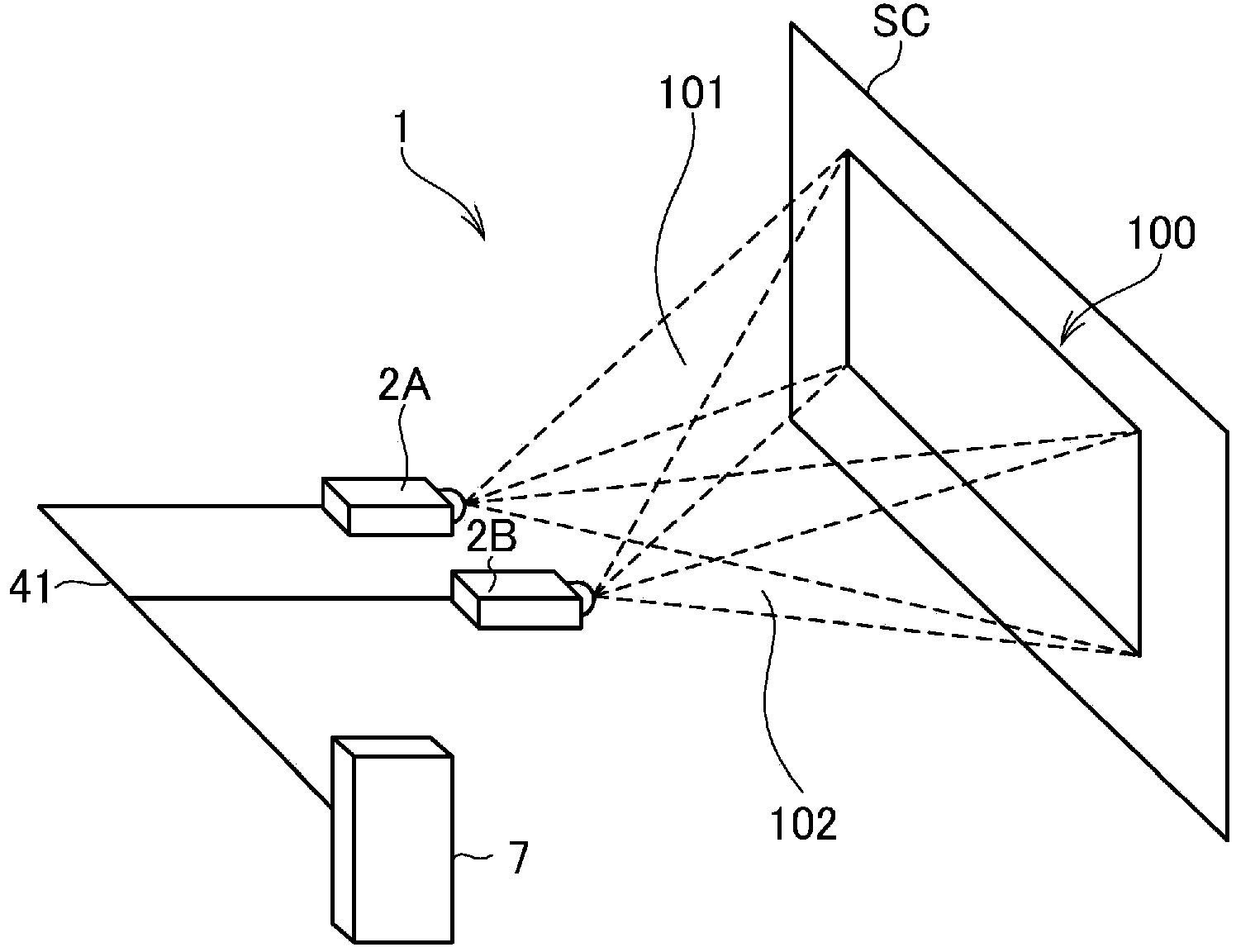
[0028] figure 1 It is a diagram showing a schematic configuration of the projection system 1 according to the embodiment of the present invention.

[0029] In the projection system 1, a projector (other projector) 2A and a projector 2B are arranged side by side, and superimposed display is performed in such a manner that the projected images 101 and 102 of the two projectors 2A and 2B overlap on the screen SC (projection surface) . In addition, in figure 1 Although the configuration in which the projectors 2A and 2B are arranged side by side is exemplified, the projectors 2A and 2B may also be arranged in a vertical arrangement. In addition, the projectors 2A and 2B may be installed on the ground (including on a stand) in front of the screen SC, or suspended from the ceiling. .

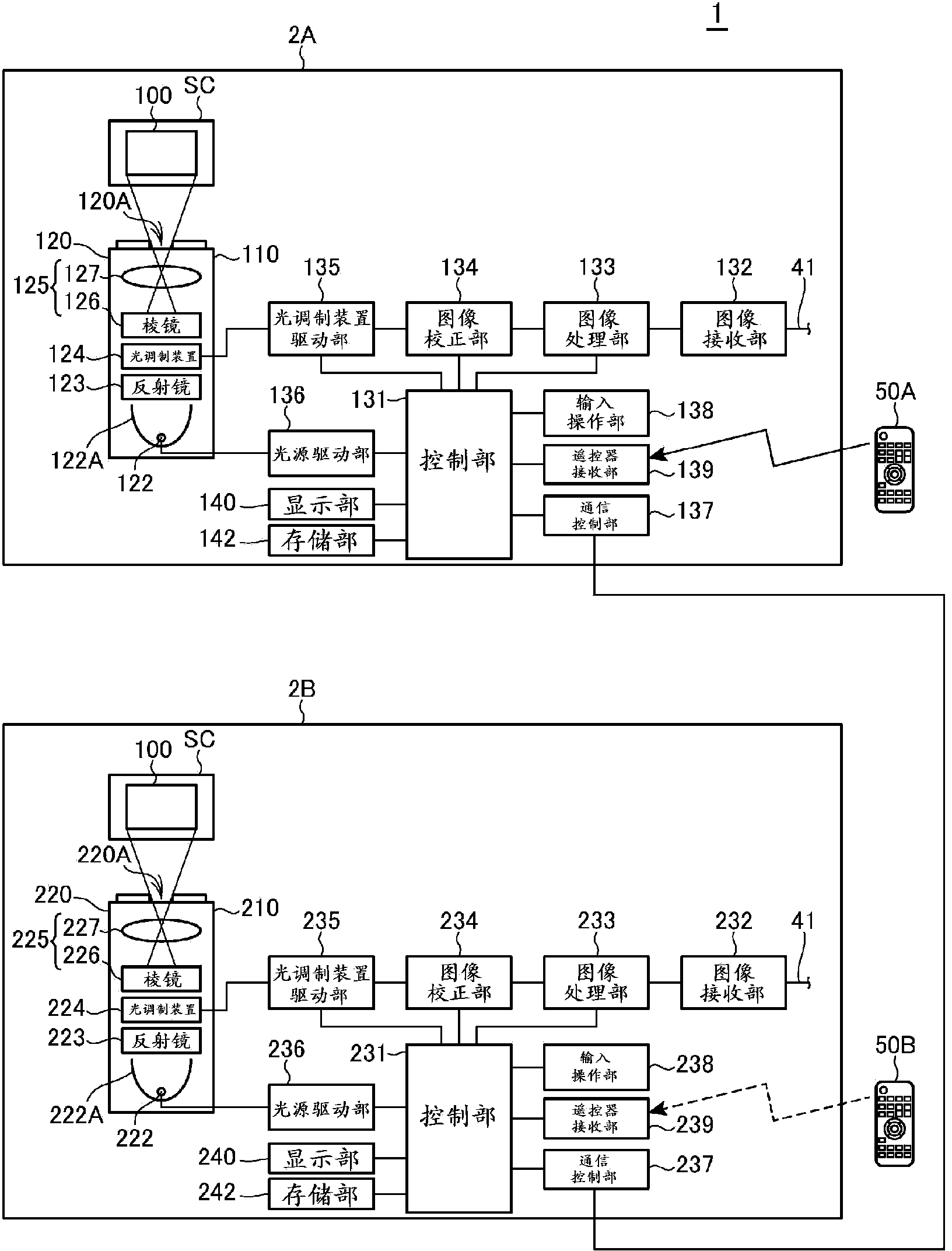
[0030] Projectors 2A and 2B are respectively connected to image outpu...


PUM


Abstract

The present invention provides a projector that performs projection in cooperation with another projector and can operate according to user operation on condition that another projector fails, and a control method for the projector. The projector (2B) is provided with a control part (231) which determines operation state of the projector (2A) and controls the projector to shift to, when the determining unit determines that the operation state of the other projector is not a normal operation state, a limited operation mode for limiting execution of at least a part of functions.

Description

technical field [0001] The present invention relates to a projector for projecting an image onto a projection surface, and a control method for the projector. Background technique [0002] Conventionally, there is known a projection system that increases the brightness of a projected image projected on a projection surface by superimposing and projecting the same image using a plurality of projectors (see, for example, Patent Document 1). In such a projection system, multiple projectors are connected in series, and one projector that receives instructions on behalf of all the projectors sends required instructions to the remaining projectors. In addition, in general, control is performed to invalidate user operations on projectors other than the instruction-accepted projector. [0003] Patent Document 1: Japanese Patent Laid-Open No. 2000-338941 [0004] However, if the projector that received the command has some abnormality and cannot perform normal operation, there is a...

Claims


Application Information

Patent Timeline
Patent Type & Authority Applications(China)
IPC IPC(8): H04N5/74G06F3/14
CPCH04N9/3147G03B21/142H04N9/3185
Inventor 有贺忠德安田裕片平透
Owner SEIKO EPSON CORP
Why Eureka
Try Eureka