Detector array with time-to-digital conversion having improved temporal accuracy

A detector array and digital converter technology, applied in the field of radiation detection, can solve the problems of fine counter output drift with time, error, reducing the effective temporal resolution of the PET detector array, etc., and achieve the effect of improving the spatial/temporal resolution

Active Publication Date: 2013-12-18
KONINKLJIJKE PHILIPS NV
View PDF8 Cites 54 Cited by
  • Summary
  • Abstract
  • Description
  • Claims
  • Application Information

AI Technical Summary

Problems solved by technology

However, spatial variation across the detector array, also known as "skew," can produce significant errors
Additionally, voltage and/or temperature variations can cause...

Method used


Image

  • Detector array with time-to-digital conversion having improved temporal accuracy
  • Detector array with time-to-digital conversion having improved temporal accuracy
  • Detector array with time-to-digital conversion having improved temporal accuracy

Examples


Embodiment Construction

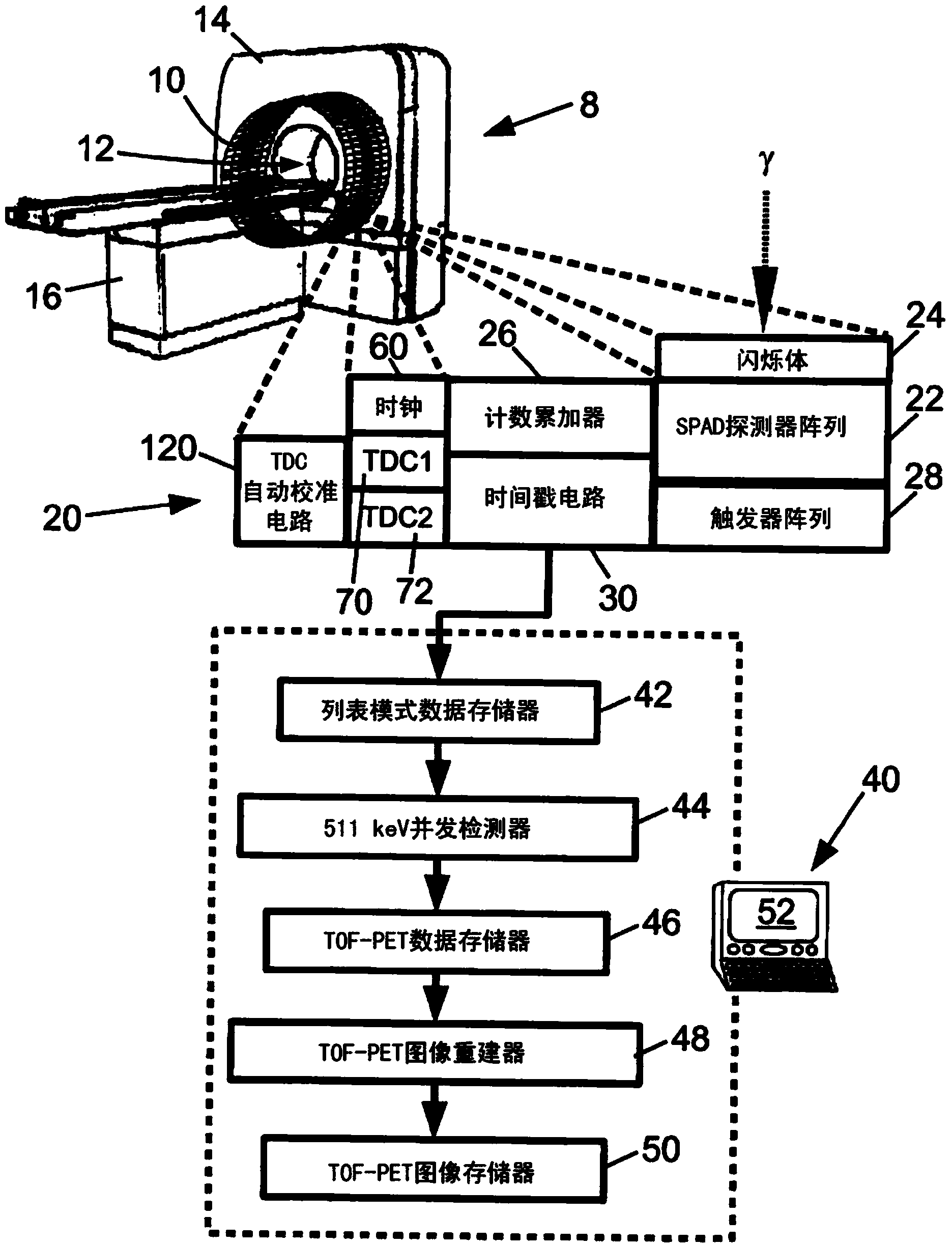
[0027] refer to figure 1 A time-of-flight positron emission tomography (TOF-PET) scanner 8 includes a plurality of radiation detectors 10 arranged to observe an imaging region 12 . exist figure 1In , a plurality of radiation detectors 10 are arranged in a circle of several detectors along the axial direction; however, other arrangements of radiation detectors can be used. Furthermore, it should be appreciated that a plurality of radiation detectors 10 are diagrammatically illustrated; typically, the radiation detectors are housed within the housing 14 of the scanner 8, and thus are not visible from the outside, and that typically, the circle of each radiation detector comprises Hundreds or thousands of radiation detectors. In some PET scanners only a single ring of radiation detectors is provided, in others two, three, four, five or more rings of radiation detectors are provided. It should be appreciated that the probe head can be substituted for the probe coil configuratio...


PUM


Abstract

A detector (22) detects an event. First and second time-to-digital converters(TDCs) (70, 72) generate first and second time stamps (TS1, TS2) for the detection of the event. The first TDC and the second TDC are both synchronized with a common clock signal (62) that defines a fixed time offset between the second TDC and the first TDC. An autocalibration circuit (120) adjusts the first TDC and the second TDC to keep the time difference between the second time stamp and the first time stamp equal to the fixed time offset between the second TDC and the first TDC. The detector may be a detector array, and trigger circuitry (28) propagates a trigger signal from a triggering detector of the array of detectors to the first and second TDC's. Skew correction circuitry (132, 134, 136, 142, 60, 162) adjusts a timestamp (TS) based on which detector is the triggering detector.

Description

technical field [0001] The following relates to the field of radiation detection. It relates in particular to high-speed radiation detectors for positron emission tomography (PET), in particular time-of-flight (TOF) PET, and will be described with particular reference thereto. However, the following relates more generally to high-speed radiation detectors for other types of radiologic imaging, and to high-speed radiation detectors for other applications such as astronomy. Background technique [0002] In PET imaging, a radiopharmaceutical administered to a human patient or other imaging subject emits positrons, each of which is in turn annihilated with electrons from surrounding imaging subjects in an electron-positron annihilation event to produce two opposite 511keV gamma rays. In conventional PET imaging, the two opposing gamma rays are detected by radiation detectors surrounding the imaged subject as two substantially simultaneous radiation detection events defining a ...

Claims


Application Information

Patent Timeline
IPC IPC(8): G01T1/29G04F10/00
CPCA61B6/037G01T1/2985G04F10/005
Inventor B·A·M·茨瓦安斯T·弗拉奇
Owner KONINKLJIJKE PHILIPS NV
Why Eureka
Try Eureka