Light condensation solar water heater device based on phase-change heat accumulation

A solar water heater and phase-change heat storage technology, which is applied to solar thermal devices, solar thermal collectors, solar thermal collectors using working fluid, etc. Injuring people and other problems, to achieve the effect of being conducive to application and promotion, convenient installation, and expanding selectivity

Active Publication Date: 2014-03-05
徐州野马锂电科技有限公司
View PDF9 Cites 6 Cited by
  • Summary
  • Abstract
  • Description
  • Claims
  • Application Information

AI Technical Summary

Problems solved by technology

The sanitation problem of solar water heaters is that the water in the water tank of the solar water heater starts to be replenished before it is exhausted, so that part of the water accumulates in the water tank of the water heater for a long time and becomes "dead water", which does not flow and causes the water quality of the water body to deteriorate. The "dead water" is repeatedly heated, and the "dead water" is in a high-temperature state for a long time, producing some carcinogenic nitrites, which are further concentrated after long-term consumption, which further aggravates the deterioration of water quality, making the water in solar water heaters not only undrinkable, Even taking a bath and washing vegetables is also very reluctant, and can only be used for washing clothes, which seriously limits the application range of solar water heaters
The installation problem of solar water heaters. The installation of solar water heaters is placed on the top of the building. It is inconvenient to install, and it cannot fit well with the building, which affects the overall image of the building. At the same time, the installation is not reliable, and there have been incidents of water heaters falling from the roof and hurting people.

Method used


Image

  • Light condensation solar water heater device based on phase-change heat accumulation

Examples


Embodiment Construction

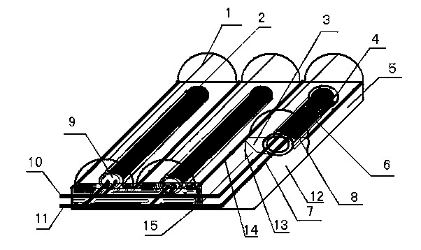
[0017] see figure 1 , the present invention includes: cylindrical lens concentrator 1, vacuum heat collecting tube 2, aluminum tank wall 3, suction belt 4, aluminum alloy outer frame 5, phase change material 6, heat exchange tube 7, heat exchange tube fin 8 , Insulation plug 9, hot water main pipe 10, cold water main pipe 11, water heater base plate 12, reinforcing rib 13, small platform 14, thermal insulation material 15. During implementation, the material of the cylindrical lens concentrator 1 is ultra-white glass with high light transmittance. After casting, grooving, and cooling treatment, an arched semi-cylinder is formed. The lower column wall of the arched semi-cylindrical body is thick, and the upper column wall is thicker. Thin, the inner wall of the cylinder is engraved with grooves, forming a Fresnel cylindrical lens, which constitutes the concentrator, determines the shape of the entire concentrator, and the focal zone of the concentrator. The cylindrical lens con...


PUM


Abstract

A light condensation solar water heater device based on phase-change heat accumulation comprises a cylindrical lens light condenser, a vacuum heat collecting pipe, a phase-change medium, two aluminum slot walls, a water heat substrate, a heat exchanging pipe, an aluminum alloy outer frame, reinforcing ribs, a small platform, a cold water main pipe, and a hot water main pipe. The cylindrical lens light condenser covers the uppermost of the vacuum heat collecting pipe. The light rays entering the cylindrical lens light condenser are condensed to form a light focal strip. The lower portion of the cylindrical lens light condenser is connected with the aluminum slot walls of the water heater substrate. The two aluminum slot walls form two plane mirrors in angled opposition. Parts of the light rays refracted by the light condenser is condensed to the vacuum heat collecting pipe, and the other parts, do not project to the vacuum heat collecting pipe, of the light rays are reflected by the two aluminum slot wall plane mirrors and projected to the vacuum heat collecting pipe. The phase-change medium and the U-shaped heat exchanging pipe are disposed inside the vacuum heat collecting pipe. The vacuum heat collecting pipe is fixedly clamped into a clamp groove formed in the water heat substrate.

Description

technical field [0001] The invention relates to the field of solar water heaters, in particular to a concentrated solar water heater device based on phase change heat storage. Background technique [0002] Today, when the global energy shortage and climate deterioration seriously threaten economic development and people's living health, all countries in the world are seeking new energy alternative strategies in order to achieve sustainable development and gain an advantage in development. With the continuous strengthening of people's awareness of energy saving and environmental protection, solar energy has quickly won the favor of consumers due to its significant advantages in safety, energy saving, environmental protection, hygiene, and economy. Solar water heaters convert sunlight energy into heat energy, and heat water from low temperature to high temperature, so as to meet the hot water use in people's life and production. Since my country introduced the sample tube of...

Claims


Application Information

Patent Timeline
Patent Type & Authority Applications(China)
IPC IPC(8): F24J2/08F24J2/05F24J2/26F24J2/34F24J2/16F24J2/46F24S10/40F24S10/75F24S23/30F24S23/77
CPCY02E10/44
Inventor 王干周兴国李鸿
Owner 徐州野马锂电科技有限公司
Why Eureka
Try Eureka