A CNC gantry planer

A gantry planer and control unit technology, applied in the direction of planer, planer/slotting machine, metal processing equipment, etc., can solve the problems of poor stability, low work efficiency, low service life, etc., achieve good stability, improve work efficiency, The effect of improving the service life

Inactive Publication Date: 2016-06-08
吕世召
View PDF11 Cites 0 Cited by
  • Summary
  • Abstract
  • Description
  • Claims
  • Application Information

AI Technical Summary

Problems solved by technology

[0003] The present invention aims at the deficiencies in the above-mentioned prior art, and provides a numerically controlled gantry planer, which overcomes the problems of low service life, poor stability, and low work efficiency

Method used


Image

  • A CNC gantry planer
  • A CNC gantry planer
  • A CNC gantry planer

Examples


Embodiment

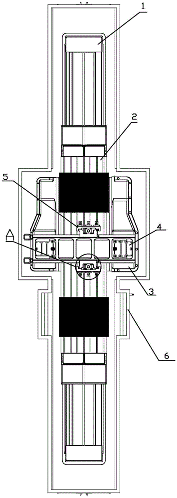
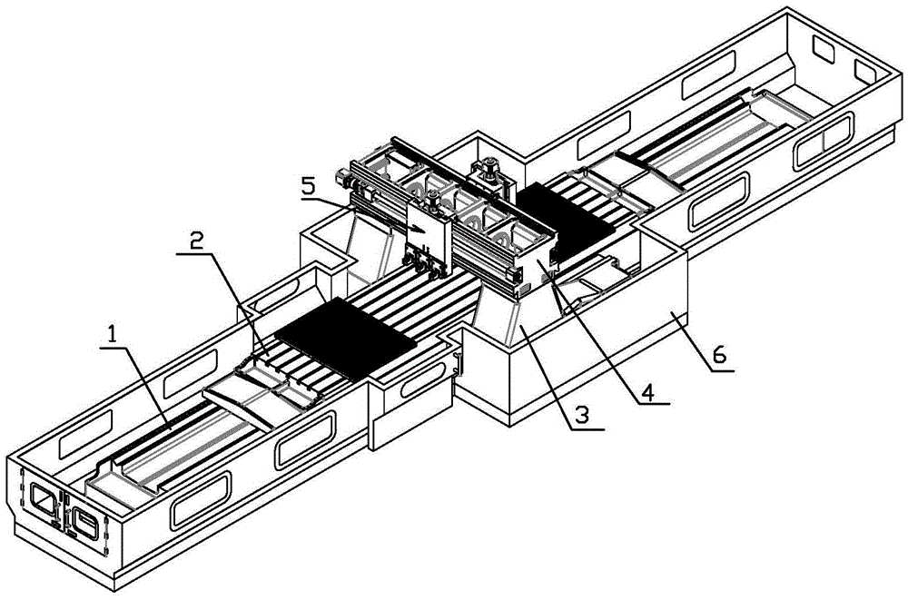
[0022] Embodiment: a kind of numerical control gantry planer, comprises gantry planer base 1, carriage 2, two left and right columns 3, crossbeam 4 and control unit, such as Figures 1 to 4 As shown, the beam 4 is fixedly arranged on the two columns 3; the motor A and the screw A are installed on the planer base 1, and the screw A is longitudinally installed on the planer base 1 through the bearing and the bearing seat. , the vertical direction refers to figure 1 In the up and down direction, the screw mandrel A is threadedly connected with a screw nut, and the screw nut is arranged on the carriage 2 through a nut seat, the motor A is connected to the screw rod A in transmission, and the motor A is connected to the control unit; the shape of the beam 4 is A cuboid, a guide rail is respectively arranged horizontally on the front and the rear of the crossbeam 4, and the horizontal direction refers to figure 1 In the left and right directions, the front of the beam 4 refers to ...


PUM


Abstract

The invention discloses a numerically-controlled double housing planer. The numerically-controlled double housing planer comprises a double housing planer base, a carriage, left and right upright columns, a cross beam and a control unit, wherein planning and cutting mechanisms are arranged on front and back sides of the cross beams, and each planning and cutting mechanism comprises a horizontal feed sliding base and a lifting carriage. According to the double housing planer, the carriage, the horizontal feed sliding bases and the lifting carriages are driven by lead screws, and the stability is higher; the planning and cutting mechanisms on two side surfaces of the cross beams are provided with independent lead screws and motors, and workpieces can be machined in a non-interfering manner, so that the working efficiency is higher; the vertical movement of a cross beam of an existing double housing planer is replaced by the vertical movement of the lifting carriages, so that the carrying load of machinery is reduced; and the problems of short service life, poor stability and low working efficiency of the existing double housing planer are solved.

Description

technical field [0001] The invention relates to the field of processing equipment, in particular to a numerically controlled planer. Background technique [0002] Gantry planer is a common equipment in the processing field. When the existing gantry planer processes parts, the beam needs to reciprocate up and down along the column. Because the weight of the beam is relatively large, it is easy to damage the rotating equipment during the up and down reciprocating movement. Moreover, the existing gantry planer The processing equipment is only set on one side of the beam, so multiple workpieces cannot be processed at the same time, and the efficiency is low; and the stability of the existing planer is poor, and the stability of the operation of the planer cannot be guaranteed, thereby affecting the machining accuracy. Contents of the invention [0003] Aiming at the deficiencies in the above-mentioned prior art, the present invention provides a numerically controlled gantry pl...

Claims


Application Information

Patent Timeline
Patent Type & Authority Patents(China)
IPC IPC(8): B23D7/00B23D7/04B23D7/10
Inventor 沈平高尔荣
Owner 吕世召
Why Eureka
Try Eureka