
Swivel Pin Mechanism

A technology of slanted pins and slanted pin seats, applied in the field of rotatable slanted pin mechanisms, can solve problems such as undercut 11 cannot be formed

Active Publication Date: 2017-02-15
SUZHOU MITAC PRECISION TECH
View PDF5 Cites 0 Cited by
  • Summary
  • Abstract
  • Description
  • Claims
  • Application Information

AI Technical Summary

Problems solved by technology

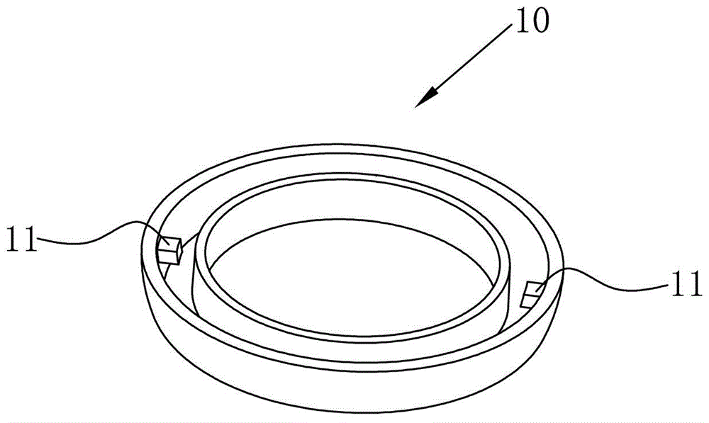
see figure 1 as shown, figure 1 The product in is a ring-shaped product 10. When there is a barb 11 in the middle of the ring-shaped product 10, the barb 11 cannot be withdrawn by using a general oblique pin, so that the barb 11 on the ring-shaped product 10 cannot be formed.

Method used


Image

  • Swivel Pin Mechanism
  • Swivel Pin Mechanism
  • Swivel Pin Mechanism

Examples


Embodiment Construction

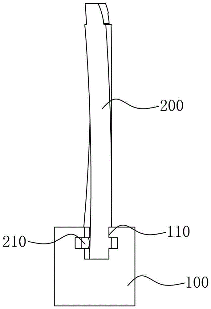
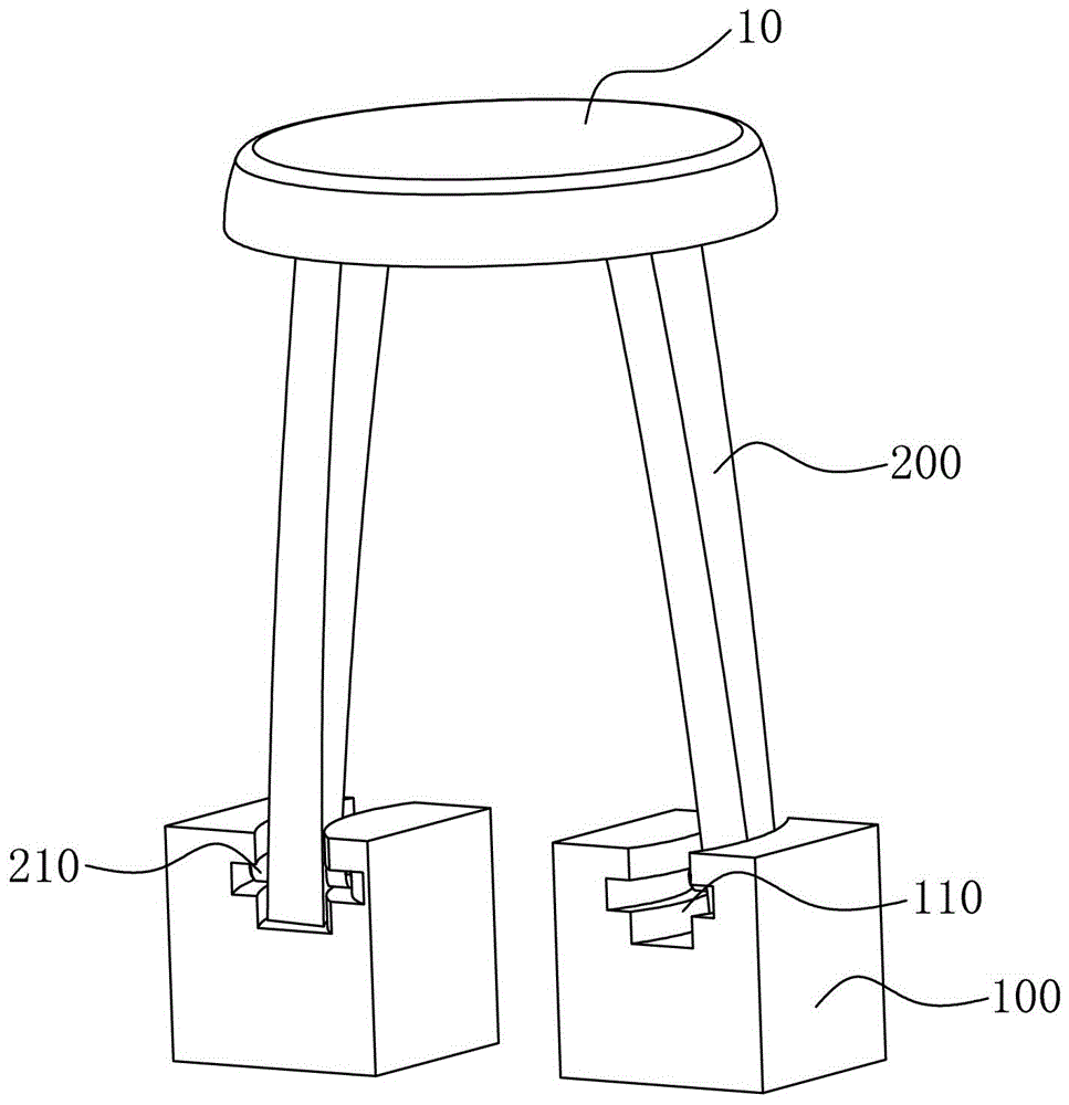
[0022] see figure 2 , image 3 and Figure 4 As shown, they respectively depict the structural schematic diagram of the swivel pin mechanism of the present invention, the schematic diagram of one angle when the product is formed by the swivel pin mechanism of the present invention, and the schematic diagram of another angle when the product is formed by the swivel pin mechanism of the present invention.

[0023] The rotary oblique pin mechanism of the present invention is applied in a mold. In this embodiment, the annular product 10 is provided with two barbs 11. Therefore, two sets of rotary oblique pin mechanisms are provided when forming the barbs 11. The swivel pin mechanism consists of:

[0024] The oblique pin seat 100, the oblique pin seat 100 is arranged on the ejection plate of the mould, and the oblique pin seat 100 is provided with an arc-shaped slot 110, the section of which is cross-shaped. When the cross-shaped arc-shaped slot 110 is used, the T-shaped arc-sh...


PUM


Abstract

The invention discloses a rotating angle pin mechanism, which is applied to a die. The rotating angle pin mechanism comprises angle pin seats and angle pins, wherein an arc clamping groove is formed in each angle pin seat; one end of each angle pin is arranged in each arc clamping groove in a rotating way, and the other end of each angle pin is matched with a product into an arc to form a reversed hook on the product. According to the rotating angle pin mechanism, the reversed hooks are upwards ejected through the angle pins when the reversed hooks in the annular product are formed, and at the same time, one end of each angle pin moves along each arc clamping groove in each angle pin seat, and the other end of each angle pin moves along the arc trajectory of the product until each reversed hook of the product is withdrawn, so that the problem that the reversed hooks in the annular product cannot be withdrawn through ordinary angle pins is solved.

Description

[0001] 【Technical field】 [0002] The invention relates to an oblique pin mechanism, in particular to a rotatable oblique pin mechanism. [0003] 【Background technique】 [0004] The plastic parts of the product will be molded using plastic molds, such as plastic parts such as housings of electronic products. Due to the popularity of electronic products, the improvement of plastic molds has also become a subject of extensive research. [0005] In the production of plastic products, it is often encountered that there are undercuts on the products, and the undercuts sometimes need to be withdrawn with oblique pins. see figure 1 as shown, figure 1 The product in is a ring-shaped product 10. When there is a barb 11 in the middle of the ring-shaped product 10, it is impossible to withdraw from the barb 11 by using a general oblique pin, so that the barb 11 on the ring-shaped product 10 cannot be formed. [0006] In view of this, it is necessary to develop a new type of swivel pin...

Claims


Application Information

Patent Timeline
Patent Type & Authority Patents(China)
IPC IPC(8): B29C33/44
Inventor 王晓鹏
Owner SUZHOU MITAC PRECISION TECH
Learn More