Shaft holder

A gripper and shaft clamp technology, applied in the direction of friction clamping detachable fasteners, connecting components, mechanical equipment, etc., can solve the problems of narrow application range, inability to achieve clamping and locking, etc. Large, good centering effect, good effect

Inactive Publication Date: 2014-05-28
BEIJING INSTITUTE OF TECHNOLOGYGY
View PDF6 Cites 10 Cited by
  • Summary
  • Abstract
  • Description
  • Claims
  • Application Information

AI Technical Summary

Problems solved by technology

[0003] The purpose of the present invention is to provide a shaft clamper to solve the problem that the existing simple clamper cannot realize clamping and locking and has a narrow application range, so as to meet the actual needs in life or industrial production

Method used


Image

  • Shaft holder
  • Shaft holder
  • Shaft holder

Examples


Embodiment 1

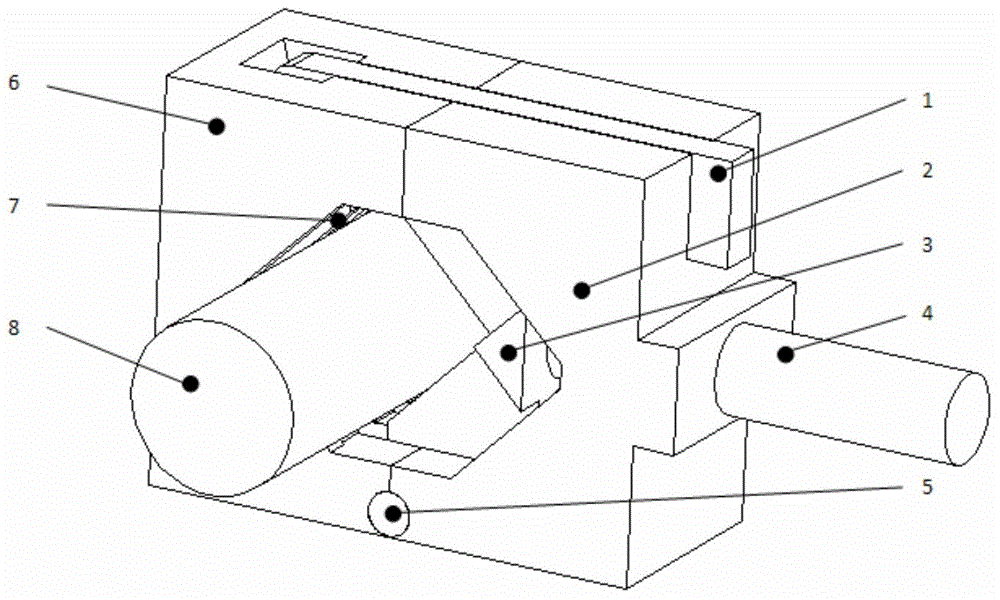
[0043] Such as figure 1 As shown, a shaft holder includes a V-shaped block, a housing and a V-shaped block compression screw 4; the V-shaped block includes a left fixed V-shaped block 7 and a right movable V-shaped block 3, and the housing It includes a left housing 6 and a right housing 2; the shaft holder also includes a left and right housing locking buckle 1; the left fixed V-shaped block 7 and the right movable V-shaped block 3 are respectively wrapped by the housing; the The left fixed V-shaped block 7 is fixedly connected with the housing; the left fixed V-shaped block 7 and the right movable V-shaped block 3 are provided with cross-arranged meshing teeth on the opposite teeth, so that the two can adapt to different The diameter range of the clamped object changes; the top of the housing is provided with a guide groove, and the right movable V-shaped block 3 is higher than the left fixed V-shaped block 7, and its higher part is embedded in the guide groove on the top of...

Embodiment 2

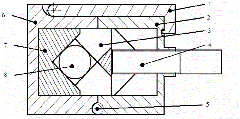
[0045] Such as figure 2 As shown, a shaft holder is similar to Embodiment 1, the difference is that the diameter of the clamped part 8 is determined by both the shell and the V-shaped block, when the V-shaped block compresses the screw 4 When moving to the rightmost end, the distance between the left fixed V-shaped block 7 and the right movable V-shaped block 3 is the largest, and the diameter of the clamped part 8 is the largest without touching the housing; when the V-shaped block compresses the screw 4 When pushed to the far left, the left fixed V-shaped block 7 and the right movable V-shaped block 3 are engaged with each other, and if the volume permits, the two can be completely engaged until the gap between them is zero; the V-shaped block presses the screw rod 4 is connected with the right housing 2 through a fine thread, and is in movable contact with the right movable V-shaped block 3 .

Embodiment 3

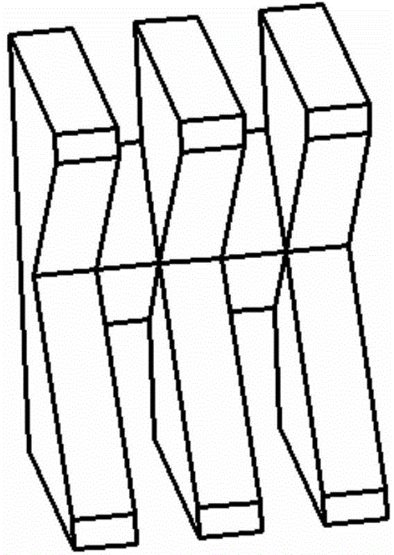
[0047] Such as Figure 3 to Figure 5 As shown, a shaft holder is similar to Embodiment 2, the difference is that the upper, lower and rear sides of the left fixed V-shaped block 7 are in contact with the inside of the left housing 6, and it passes through the two middle parts. A countersunk head bolt is fixed on the left housing 6, and the bolt only plays a positioning role, and does not bear compressive force or tensile stress during the clamping process.


PUM


Abstract

The invention relates to a shaft holder comprising a V-shaped block, a shell, a V-shaped block compressing screw and a left and right shell body locking latch. The V-shaped block comprises a left fixed V-shaped block and a right movable V-shaped block, the shell comprises a left shell body and a right shell body, the left fixed V-shaped block and the right movable V-shaped block are wrapped by the shell body, the left fixing V-shaped block is fixedly connected with the shell body, mesh teeth in cross banding are evenly arranged on a teeth mouth portion corresponding to the left fixed V-shaped block and the right movable V-shaped block, so that the left fixed V-shaped block and the right movable-V shaped block can be meshed correspondingly to adaptive to diameter range changes of different clamping targets; the shaft holder is capable of solving the problem that the existing simple shaft holder cannot lock tightly and is narrow in application range, and meeting actual demand in real life or industry production.

Description

technical field [0001] The invention belongs to the technical field of clamping devices, and relates to a clamper, in particular to a shaft clamper. Background technique [0002] In daily life and industrial production, it is often encountered that a small object is clamped or adsorbed to a shaft, and it is required to be fixed. For example, in daily life, the movable table lamp or fan is clamped to the beam. At present, ordinary spring clamps are generally used for installation. In industry, when dual motors are installed coaxially, the magnetic dial base of the dial indicator needs to be adsorbed on the beam. On one motor shaft, detect the coaxiality between the other motor and the motor shaft, so as to adjust the height or position of the mounting seat. However, the above existing installation methods have their own limitations. For example, ordinary spring clips cannot effectively clamp large or small shafts, especially optical shafts, and magnetic mounts cannot provide...

Claims


Application Information

Patent Timeline
Patent Type & Authority Applications(China)
IPC IPC(8): F16B2/18
Inventor 宋强罗淋王文俊赵凭曾普
Owner BEIJING INSTITUTE OF TECHNOLOGYGY
Why Eureka
Try Eureka