Tong-type automatic unhooking device

A technology of automatic decoupling and driving device, applied in the field of automatic decoupling device of pliers hook and lifting traction device, can solve the problems of low safety performance, violent swing of decoupling device, inaccurate position of drop point, etc. Accurate position, safe and reliable work, simple and compact structure

Active Publication Date: 2011-02-16
CEEC JIANGSU ELECTRIC POWER DESIGN INST
View PDF4 Cites 10 Cited by
  • Summary
  • Abstract
  • Description
  • Claims
  • Application Information

AI Technical Summary

Problems solved by technology

The single-hook flip-type decoupling device will generate lateral force when decoupling, causing the decoupling device to swing violently after decoupling. After the heavy object is decoupled, it is easy to cause space drift, the landing point position is inaccurate, and the neutrality is relatively poor. It is mainly used for heavy objects. Occasions where the position of the landing point is not high
Chinese patent document CN92223321.7 discloses an automatic uncoupling device, which belongs to the single-hook flip type uncoupling device, which improves the sensitivity of decoupling and overcomes the space drift caused by the decoupling of heavy objects, but the safety performance is not high
Chinese patent document CN87209663 discloses a load and unloading uncoupling device, which belongs to the pincer type uncoupling device. The technical scheme is simple in structure, and it is indeed better when the requirements for the unloading position are not high, but it is inconvenient to operate and the safety performance is not good. High, it is not suitable for applications such as test detection and other fields that require high neutrality
In short, the current decoupler still has the problems of inconvenient operation, difficult remote control, poor safety, and inaccurate unloading position.

Method used


Image

  • Tong-type automatic unhooking device
  • Tong-type automatic unhooking device
  • Tong-type automatic unhooking device

Examples


Embodiment 1

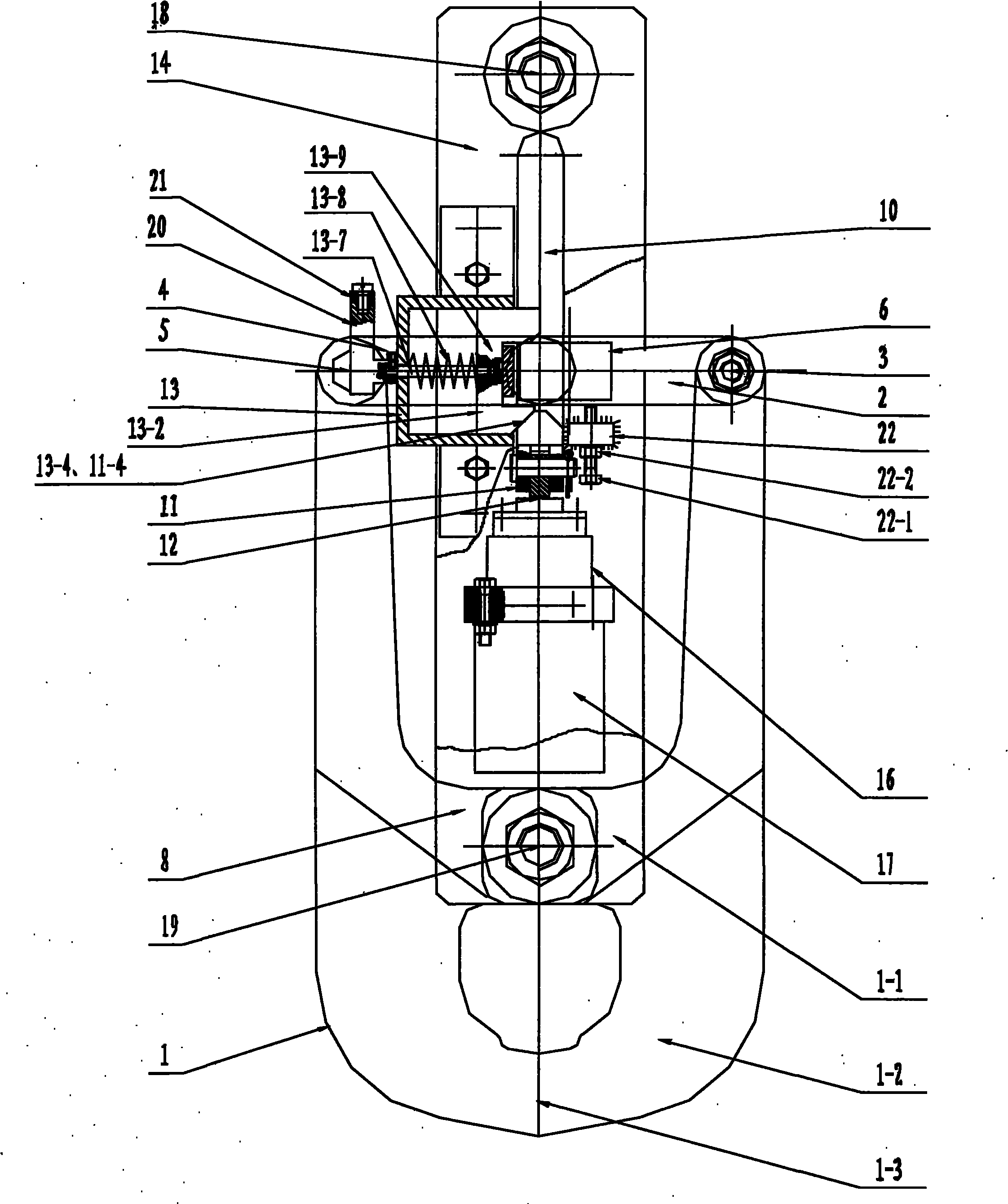
[0038] Such as figure 1 , figure 2 , image 3As shown, the pliers-type automatic decoupling device of the present invention comprises two symmetrically arranged tongs 1, wherein one end of one tongs 1 is hinged with the first connecting rod 2 through the first hinge 3, and one end of the other tongs 1 is connected to The second connecting rod 4 is hinged by the second hinge 5, and the other ends of the first connecting rod 2 and the second connecting rod 4 are all connected with the slider shaft 6, and one end of the slider shaft 6 is connected with the opening slider 7, and the slider shaft 6, The opening slide block 7 is placed in the chute 10 on the first pull plate 8 and the second pull plate 9, and a push rod 11 is also provided in the chute 10, on the side of the push rod 11 that is different from the slide block shaft 6 Connect the coupling shaft 12, the other end of the slider shaft 6 is locked in the self-locking device 13, the self-locking device 13 is arranged on...

Embodiment 2

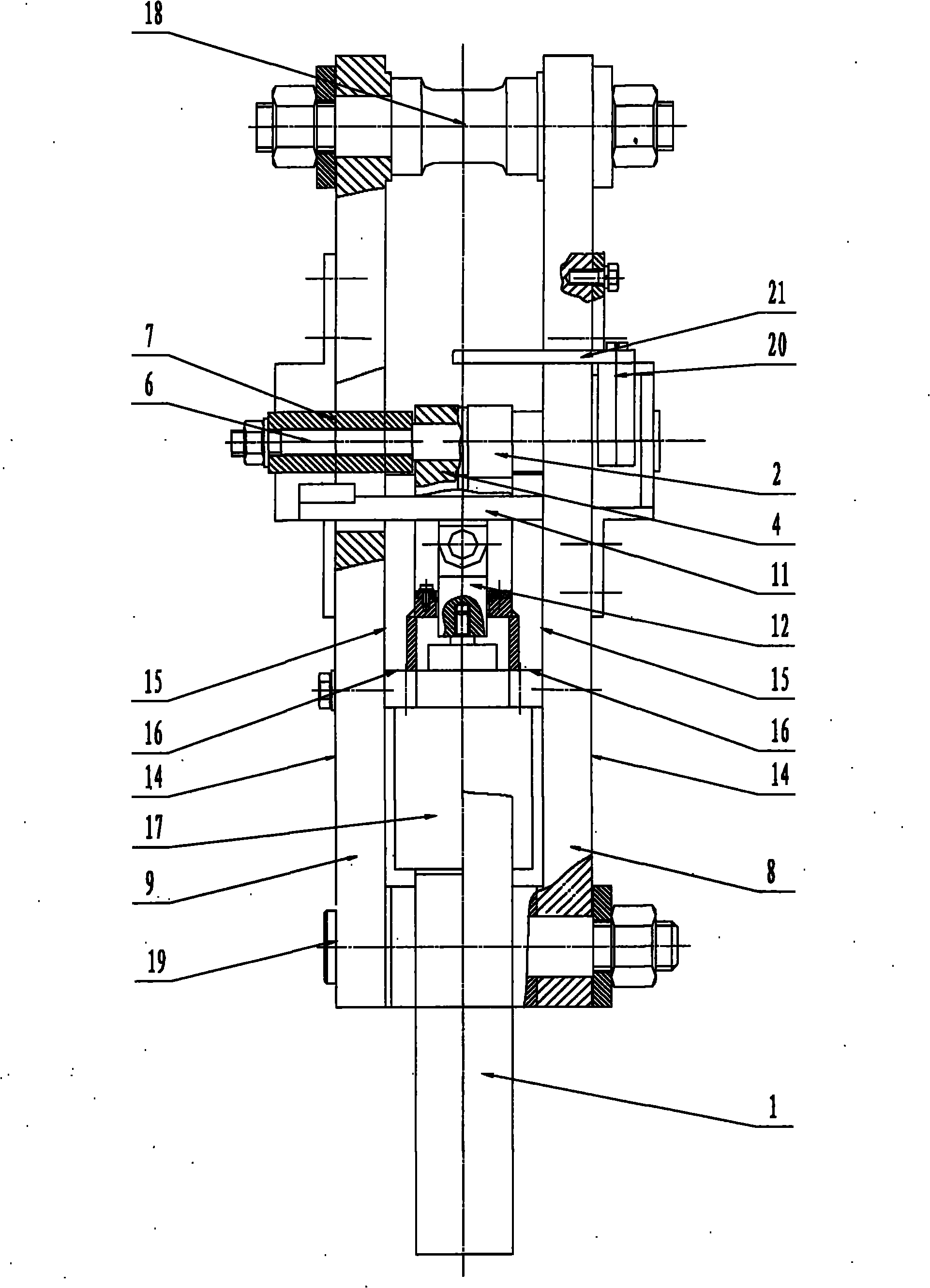
[0040] On the basis of embodiment 1, the preferred embodiment of the present invention is, as figure 1 , Figure 4-Figure 7 As shown, the self-locking frame 13-1 of the self-locking device 13 is located on the outer surface 14 of the first pull plate 8, and the self-locking slider 13-2 is placed in the self-locking frame 13-1, and is connected with the self-locking frame 13-1. Sliding fit, self-locking slide block 13-2 is groove 13-3 shape, groove 13-3 one end boss is provided with an inclined-plane 13-4, and groove 13-3 is stuck in the inner baffle plate 13-5, automatically The groove bottom plate of lock slider 13-2 links to each other with pull bar 13-7, and pull bar 13-7 passes through outer baffle plate 13-6 and links to each other with handle 20, and the other end of handle 20 links to each other with handle linkage 21, and pull bar 13-7 overcoat has Spring 13-8, spring 13-8 is placed between self-locking slide block 13-2 and outer baffle plate 13-6, and all the other a...

Embodiment 3

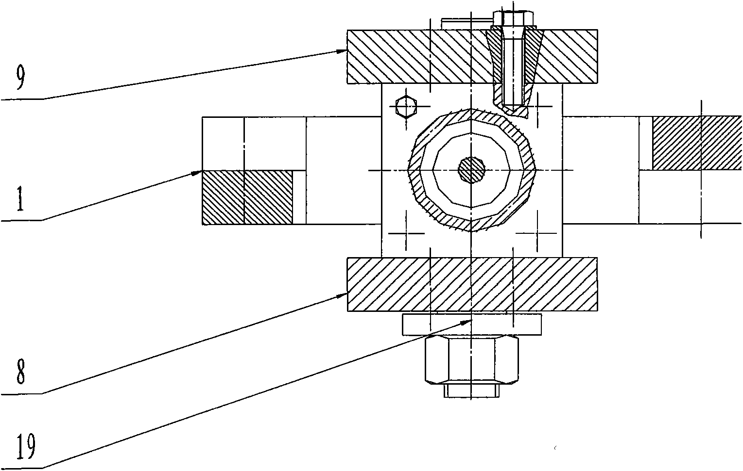
[0042] On the basis of embodiment 2, the preferred embodiment of the present invention is, as figure 1 , Figure 8 As shown, the first pull plate 8 and the second pull plate 9 are oblate cuboids with the same structure, correspondingly arranged, the chute 10 is an oblong transparent groove, and the chute 10 is arranged at one end of the connecting pin shaft 18 of the pull plates 8 and 9 Between the connection bracket 16, the rest are exactly the same as the implementation 2.


PUM


Abstract

The invention discloses a tong-type automatic unhooking device which belongs to the technical field of mechanical lifting and towing devices. The invention is characterized in that two tong pieces are symmetrically arranged; one end of each tong piece is hinged with one end of a connecting rod; the other end of the connecting rod is connected with a sliding block shaft; one end of the sliding block shaft is connected with an opening sliding block; the sliding block shaft and the opening sliding block are arranged in a sliding chute on a first drawplate and a sliding chute on a second drawplate; a post rod is also arranged in the sliding chute; one side of the post rod, which is different from the sliding block shaft, is connected with a connecting shaft; the other end of the sliding block shaft is locked in a self-locking device; the self-locking device is arranged on the outer side surface of the first drawplate; the inner side surfaces of the first drawplate and second drawplate are connected with a bracket; the bracket is connected with a drive unit linear stepping motor; one end of the first drawplate is connected with one end of the second drawplate through an axis pin; and the other ends of the first drawplate and second drawplate are hinged with the tong pieces. The device has the advantages of simple structure, small opening force, convenient operation, safe and reliable operation, accurate unhooking landing point and favorable centering performance, and can be remotely controlled.

Description

technical field [0001] The invention relates to a hook of a lifting and pulling device, in particular to a clamp-type hook automatic decoupling device, which belongs to the technical field of mechanical lifting and pulling devices. Background technique [0002] The hook used to connect the load in the lifting traction mechanism is very convenient when loading, but it is more troublesome when unloading. As an improved form of the hook, the commonly used decoupling device has two basic forms: clamp type and single hook flip type. The single-hook flip-type decoupling device will generate lateral force when decoupling, causing the decoupling device to swing violently after decoupling. After the heavy object is decoupled, it is easy to cause space drift, the landing point position is inaccurate, and the neutrality is relatively poor. It is mainly used for heavy objects. Occasions where the position of the landing point is not high. Chinese patent document CN92223321.7 discloses ...

Claims


Application Information

Patent Timeline
Patent Type & Authority Applications(China)
IPC IPC(8): B66C1/34
Inventor 蔡升华刘欣良戴洪军王学林周伟
Owner CEEC JIANGSU ELECTRIC POWER DESIGN INST
Why Eureka
Try Eureka