
Device for testing feeding force and lifting force of top-drive power head drill

A technology of testing device and feeding force, which is applied in the direction of measuring device, force/torque/work measuring instrument, instrument, etc., can solve the problems of eccentricity between drilling rig and testing device, rig stability and tediousness, etc., and achieve good neutrality and reduce testing effect of error

Inactive Publication Date: 2012-07-04
XIAN RES INST OF CHINA COAL TECH& ENG GROUP CORP
View PDF5 Cites 10 Cited by
  • Summary
  • Abstract
  • Description
  • Claims
  • Application Information

AI Technical Summary

Problems solved by technology

[0003] The technical problem solved by the present invention is to provide a method for testing the power head that solves the cumbersome stability of the existing drilling rig and the eccentricity of the drilling rig and the testing device, can effectively simplify the drilling rig stabilization procedure, and ensure the concentricity of the drilling rig power head and the testing device. Test device for feed force and pull-out force of type drilling rig

Method used


Image

  • Device for testing feeding force and lifting force of top-drive power head drill
  • Device for testing feeding force and lifting force of top-drive power head drill
  • Device for testing feeding force and lifting force of top-drive power head drill

Examples


Embodiment Construction

[0016] The present invention will be described in detail below in conjunction with the accompanying drawings and specific embodiments.

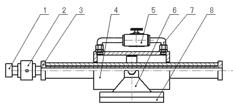
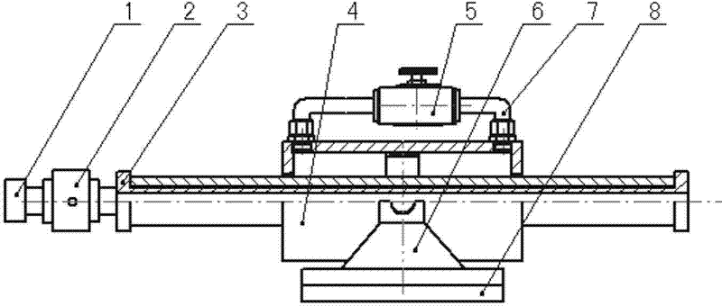
[0017] see figure 1 , 2 , the present invention includes an oil cylinder 4, a force transmission mandrel 3, a hinge support 6, and a backing plate 8, the oil cylinder 4 is arranged on the hinge support 6 and a backing plate 8 is arranged at the bottom of the hinge support 6, and the piston rod of the oil cylinder 4 is a hollow structure , the force transmission mandrel 3 is arranged in the piston rod, and the end of the force transmission mandrel 3 is provided with a tension pressure sensor 2; the bottom of the backing plate 8 of the test device is arranged on the guide rail of the rig body through the holder seat 9 10 , the test drill pipe 12 supported by the power head of the drilling rig is connected with the tension pressure sensor 2 through the drill pipe adapter 1 .

[0018] The above-mentioned testing device is concentric with the dr...


PUM


Abstract

The invention relates to a device for testing feeding force and lifting force of a top-drive power head drill. At present, a device for testing the feeding force and the lifting force of the top-drive power head drill is required to reliably fix the drill, as well as ensuring the center of the power head of the drill is concentric with the testing device, but both are hard to realize, which results in that the drill shaft is likely to arch to influence the testing precision during testing the feeding force. The device comprises an oil cylinder, a force transmission core bar, a hinge bearing and a base plate, wherein the oil cylinder is arranged on the hinge bearing, and the base plate is mounted at the bottom of the hinge bearing; a piston rod of the oil cylinder is of a hollow structure and is provided internally with the force transmission core bar, and a pulling pressure sensor is mounted at the tail end of the force transmission core bar; the bottom of the base plate of the testing device is arranged on a guide rail on the drill body through a holder bearing; and a testing drilling rod held by the power head of the drill is connected with the pulling pressure sensor. With the testing device provided by the invention, the drill fixation is unnecessary; centering of the device relative to the power head of the drill is good, and thus the testing error is reduced.

Description

technical field [0001] The invention relates to a testing device for testing the feeding force and pulling-out force of a power head drill. Background technique [0002] When inspecting the capability of the power head drilling rig, the feeding and pulling capacity of the power head drilling rig are usually tested. At present, the feeding and pulling capacity testing devices of the power head drilling rig are mainly fixed on the special drilling rig test bench In general, the structural feature of this test device is that the tension pressure sensor is connected to the piston rod end of the single-rod double-acting cylinder, and the feeding force and pulling force of the power head drilling rig are applied to the tension pressure sensor through the drill pipe and the drill pipe adapter. , The oil inlet and outlet of the oil cylinder are each connected in series with a throttle valve. By adjusting the opening size of the throttle valve, the oil return pressure is adjusted to ...

Claims


Application Information

Patent Timeline
IPC IPC(8): G01L5/00
Inventor 殷新胜宋海涛冀前辉孙保山刘桂芹
Owner XIAN RES INST OF CHINA COAL TECH& ENG GROUP CORP
Learn More