
Creep compression experimental apparatus

An experimental device and creep test technology, which is used in measuring devices, instruments, scientific instruments, etc., can solve the problems of insufficient clamping accuracy of rod-shaped samples, inability to accurately measure creep experiments, and damage to the measuring head of displacement sensors. Risk of specimen instability and sensor damage, reduction of likelihood and risk of sensor damage, reduction of possible effects of specimen bending

Active Publication Date: 2019-06-11
CENT SOUTH UNIV
View PDF36 Cites 10 Cited by
  • Summary
  • Abstract
  • Description
  • Claims
  • Application Information

AI Technical Summary

Problems solved by technology

[0004] The authorized utility model patent CN 206990327U provides a compression fixture for a uniaxial tensile creep testing machine. This scheme uses the existing uniaxial tensile creep testing machine to realize the test of material compression creep performance. This method is suitable for thick and short, The creep performance test of samples with a large diameter-to-height ratio, but the test of slender samples with uneven end surfaces has great limitations. On the indenter, the coincidence with the sample axis is poor, and the test accuracy of the creep value is not high through the displacement of the indenter.
The authorized utility model patent CN 204422329U discloses a compression fixture on a mechanical tensile creep testing machine. This invention can complete the compression creep test on the existing mechanical tensile creep endurance testing machine. One end of the sample is connected with the adjustment Ball head contact, when the parallelism of both ends of the sample is not high, the ball head plane is not horizontal, the force is not horizontal to the axis, and the spherical contact does not restrict the rotation, and the sample is easy to bend in the compression test
The authorized utility model patent CN 207147874U relates to a fixture for testing compression creep aging on an electronic universal testing machine. When the fixture is used for testing, the sample itself does not need to be clamped, and it only needs to be placed in the place where the sample is clamped. It is easy to use. However, this fixture is only suitable for linear samples. For rod-shaped samples with external threads at both ends, the clamping accuracy is not enough, and the threads are easy to be damaged, which will affect the subsequent experiments. Moreover, the structure of the fixture is relatively complicated, and the experimental operation space is small , it is not easy to install the sample and has a significant impact on the distribution of the temperature field, which is not conducive to carrying out creep experiments in the creep machine
The authorized invention patent CN 107063851A discloses a high-temperature compression fixture. This patent provides a test fixture for testing material compression performance indicators in a high-temperature environment. The tensile force is converted into pressure through cross-connected upper and lower compression bodies. The compression performance test is carried out by means of tension, but the two ends of the fixture sample are not fixed, and it is easy to cause sliding to cause the sample to bend, and the whole fixture needs to be disassembled when carrying out the experiment, which is inconvenient for actual operation, and frequent disassembly will affect the The fixture itself has a great influence and shortens the service life
The authorized utility model patent CN203798673U provides a test fixture for testing the compression performance index of materials in high temperature environment. The fixture uses the principle of relative motion to realize the method of converting the tensile performance test of the material into the compression performance test. The briquettes are squeezed together to compress the sample. This fixture cannot be centered when performing a slender rod-shaped sample test. There is no clamping device at both ends of the sample, so the displacement of the creep test cannot be accurately measured, and the sample is relatively large. It is difficult to process the fixture cavity and through holes for a long time, the cost is high, and the accuracy is difficult to guarantee, which has a great impact on the results of creep experiments that require high displacement accuracy
[0005] The authorized invention patent CN 104374646A discloses a mechanical creep extensometer, which provides a new extensometer that can clamp bar samples with different diameters and different gauge lengths. Good versatility and high measurement accuracy, but when carrying out the compression test, the compression of the sample is converted into the compression of the sensor head. When the sample becomes unstable and bent, the compression will increase rapidly, exceeding the stroke of the measuring head, resulting in high Damage to precision displacement sensors
The authorized utility model CN ​​201016904Y discloses a metal room temperature creep test tool, which can measure the elongation of the creep sample. The working process is stable and the volume is small. However, the tool needs to be in the same environment as the At room temperature, the high temperature creep test cannot be carried out, and the precision displacement sensor will be damaged when the sample is unstable and damaged
The authorized utility model CN207703621U relates to a quick-clamping extension device for creep tests. Through simple operation, it can meet the test assembly requirements and improve the clamping speed. However, when carrying out compression tests, the high-precision displacement sensor is located in the test On both sides of the sample, the instability and bending of the sample will cause the sensor to over-travel, which in turn will cause damage to the high-precision displacement sensor
[0006] In summary, there is a need for a solution in the prior art to solve the problems of instability and bending caused by the misalignment of the force and axis of the sample that are prone to occur during creep compression experiments, as well as the displacement after instability and bending. The problem that the sensor measuring head is damaged due to overtravel

Method used


Image

  • Creep compression experimental apparatus
  • Creep compression experimental apparatus
  • Creep compression experimental apparatus

Examples


Embodiment Construction

[0029] The embodiments of the present invention will be described in detail below with reference to the accompanying drawings, but the present invention can be implemented in various ways defined and covered by the claims.

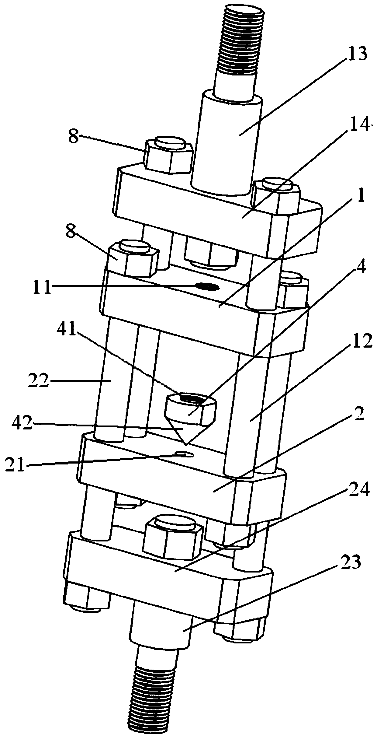
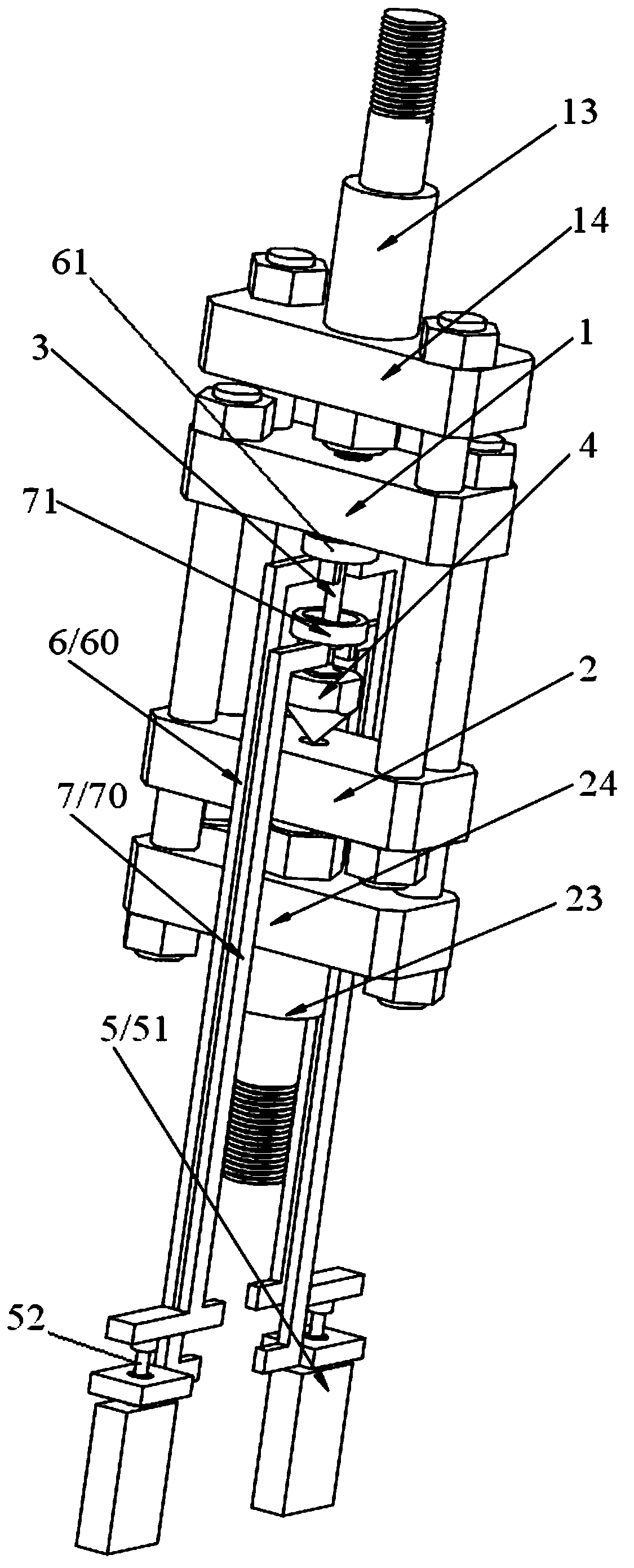
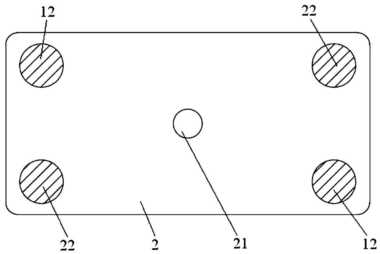
[0030] see Figure 1 ~ Figure 3 The creep compression experimental device comprises the mounting frame used to be connected between the upper and lower two tension rods (ie the upper tension rod and the lower tension rod, not shown in the figure) of the creep testing machine, the mounting frame Including the upper pressing block 1 and the lower pressing block 2, there is a distance between the upper pressing block and the lower pressing block along the stretching direction of the creep testing machine for installing the sample 3, and the spacing value can be set in the creep testing machine Adjustment under the drive of the lower tensile rod, the distance can be reduced to provide creep compression loading operation on the specimen, and the distance can be...


PUM


Abstract

The invention provides a creep compression experimental apparatus. The creep compression experimental apparatus comprises an installation frame connected between an upper stretching rod and a lower stretching rod of a creep test machine, wherein the installation frame comprises an upper pressure block and a lower pressure block, the upper pressure block is provided with a threaded hole A, the lower pressure is provided with a conical hole coaxial with the threaded hole A, one end of a test sample is fixed in the threaded hole A, the other end is located in the conical hole by virtue of a conical head of a conical positioning device, and when the conical head is matched with the conical hole, the threaded hole A, the conical head, the conical hole and the test sample are coaxial. The auto-positioning function is realized by virtue of a conical surface contact of the conical positioning device, so that the test sample can be well centralized in the single-axis compression process, and the instability bending possibility of the test sample can be reduced. By virtue of the reversely-arranged extension rod, the rebound displacement of a precompressed sensor measuring head in the reset process is taken as the compression creep deformation of a sample, so that the occurrence of overstroke of the sensor measuring head and damage to the displacement sensor can be effectively avoided.

Description

technical field [0001] The invention relates to creep experiment equipment, in particular to a creep compression experiment device. Background technique [0002] With the rapid development of the aviation industry, the requirements for aircraft performance continue to increase. The original deformation processing technology (roll bending, stretching, etc.) Variable aging forming technology came into being. Creep aging forming technology will have tension-compression asymmetry problems in the realization of component forming. In order to ensure component forming accuracy, good strength, and high corrosion resistance, it is necessary to study the creep tension-compression properties of samples with the same material as the component. [0003] In order to carry out the creep compression test, the existing scheme is as follows: [0004] The authorized utility model patent CN 206990327U provides a compression fixture for a uniaxial tensile creep testing machine. This scheme use...

Claims


Application Information

Patent Timeline
Patent Type & Authority Applications(China)
IPC IPC(8): G01N3/28G01N3/02
CPCY02E30/30
Inventor 湛利华郑启朋汪凯黄明辉
Owner CENT SOUTH UNIV
Learn More