A short circuit fault current limiter

A short-circuit fault, current limiter technology, applied in circuit devices, emergency protection circuit devices, emergency protection circuit devices for limiting overcurrent/overvoltage, etc., to achieve low impedance, good current limiting effect, and improved reliability. Effect

Active Publication Date: 2016-08-17
INST OF ELECTRICAL ENG CHINESE ACAD OF SCI
View PDF6 Cites 0 Cited by
  • Summary
  • Abstract
  • Description
  • Claims
  • Application Information

AI Technical Summary

Problems solved by technology

The resonant current limiter is accompanied by high voltage during the current limiting process, which poses a great safety hazard

Method used


Image

  • A short circuit fault current limiter
  • A short circuit fault current limiter
  • A short circuit fault current limiter

Examples


Embodiment Construction

[0021] The present invention will be further described below in conjunction with accompanying drawing and specific embodiment:

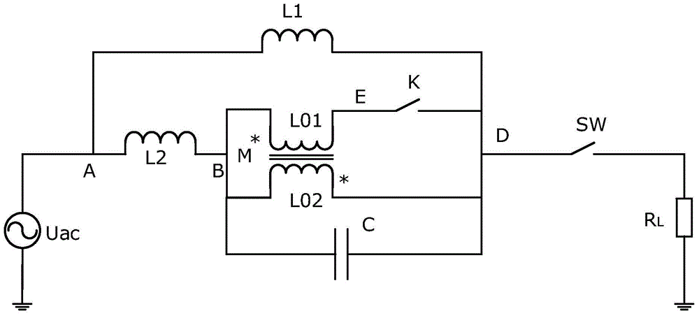
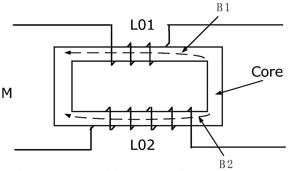
[0022] like figure 2 As shown, the specific embodiment 1 of the present invention is a single-phase short-circuit fault current limiter. The single-phase short-circuit fault current limiter includes a first reactor L1, a second reactor L2, a double split reactor M, a capacitor C and a switch K. Wherein, the double-split reactor M is composed of a first winding L01 and a second winding L02.

[0023] After the first winding L01 of the double-split reactor M is connected in series with the switch K, it is connected in parallel with the second winding L02, and then connected in parallel with the capacitor C. This parallel circuit is connected in series with the second reactor L2, and the entire series-parallel circuit is connected with the first reactor L1 in parallel. Among them, one end of the first reactor L1 and one end of the second reactor L2 a...


PUM


Abstract

The invention discloses a short-circuit fault current limiter and relates to a short-circuit fault current limiter for a transmission and distribution power grid. The short-circuit fault current limiter is composed of a first electric reactor, a second electric reactor, a double-splitting electric reactor, a capacitor and a switch, wherein a first winding of the double-splitting electric reactor is connected with a second winding in parallel after being connected with the switch in series and then is connected with the capacitor in parallel, a parallel circuit is connected with the second electric reactor in series, and the whole series-parallel circuit and the first electric reactor are connected in parallel to form the short-circuit fault current limiter. According to the short-circuit fault current limiter, through the cooperation between the double-splitting electric reactor and the switch, impedance change and rapid short circuit of the capacitor are achieved during current limiting, the electric reactors are put into use fast, overcurrent impact and overvoltage impact when the double-splitting electric reactor cooperates with the switch are relieved through the parallel connection of the first electric reactor, and the operating reliability and the current limiting capacity of the limiter are improved.

Description

technical field [0001] The invention relates to a short-circuit fault current limiter, in particular to a short-circuit fault current limiter for a transmission and distribution network. Background technique [0002] With the rapid development of the national economy, the society's demand for electricity continues to increase, which drives the continuous development of the power system. The capacity of single machines and power plants, the capacity of substations, and the load of cities and industrial centers continue to increase, which makes the interconnection of power systems , the level of short-circuit current in the power grid at all levels is increasing continuously, and the destructiveness of short-circuit faults to the power system and its connected electrical equipment is also increasing. Moreover, while the demand for electric energy is increasing day by day, people also put forward higher requirements for power quality, power supply reliability and security. How...

Claims


Application Information

Patent Timeline
Patent Type & Authority Patents(China)
IPC IPC(8): H02H9/02
Inventor 肖立业张志丰邱清泉李耀华马韬周薇薇许熙靖立伟朱志芹张国民戴少涛严萍
Owner INST OF ELECTRICAL ENG CHINESE ACAD OF SCI
Why Eureka
Try Eureka