

A signal detection method and device applied to a multi-input multi-output system
A signal detection, multi-output technology, applied in the field of communication, can solve the problem of not being able to achieve bit error rate performance, unable to achieve optimal bit error rate performance, etc., and achieve the effect of avoiding bit error rate performance
- Summary
- Abstract
- Description
- Claims
- Application Information
AI Technical Summary
Problems solved by technology
Method used
Image

Examples
Embodiment 1
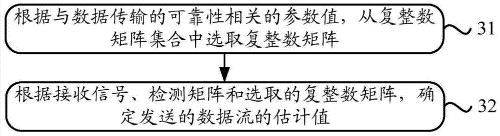
[0049] In order to solve the problem in the prior art that LRA detection for signals cannot achieve optimal bit error rate performance, Embodiment 1 of the present application provides a signal detection method applied to a multiple-input multiple-output system. The specific implementation flow chart of this method is as follows: image 3 As shown, it mainly includes the following steps:
[0050] Step 31: Select a complex integer matrix from the set of complex integer matrices according to the parameter values related to the reliability of data transmission.
[0051]Wherein, the above-mentioned parameter values related to the reliability of data transmission may be, but not limited to, the value of the signal to interference plus noise ratio (Signal to Interference plus Noise Ratio, SINR) of the data streams transmitted by different transmitting antennas at the receiving end, the mean square error ( Mean Squared Error, MSE) value or Bit Error Rate (Bit Error, BER) value. ...
Embodiment 2
[0147] Embodiment 2 provides a signal detection device applied to a multiple-input multiple-output system to solve the problem in the prior art that LRA detection for signals cannot achieve optimal bit error rate performance. The specific structure diagram of the signal detection device is as follows: Figure 4 As shown, a matrix selection unit 41 and a transmission signal determination unit 42 are included. The specific introduction of these two functional units is as follows:
[0148] The matrix selection unit 41 is configured to select a complex integer matrix from a set of complex integer matrices according to parameter values related to the reliability of data transmission. Wherein, the set of complex integer matrices is composed of complex integer matrices obtained by decomposing the channel matrix.
[0149] The transmission signal determination unit 42 is used to determine the estimated value of the transmitted data stream according to the received signal, the detec...
PUM
 Abstract
Description
Claims
Application Information