Check patentability & draft patents in minutes with Patsnap Eureka AI!

A Wide Viewing Angle Integrated Imaging 3D Display System

An integrated imaging and three-dimensional display technology, applied in stereoscopic systems, image communication, optics, etc., can solve the problems of complex structure, control, limited viewing angle and viewing effect of the display system, and difficult realization, so as to reduce complexity and manufacture Difficulty, increasing the display range and resolution, and improving the viewing angle

Inactive Publication Date: 2017-02-08
XIDIAN UNIV
View PDF6 Cites 0 Cited by
  • Summary
  • Abstract
  • Description
  • Claims
  • Application Information

AI Technical Summary

Problems solved by technology

[0004] Integrated imaging 3D display can often obtain a high-resolution unit image array through camera array or computer rendering generation technology at the acquisition end, but at the reconstruction end, it is restricted by the display device, and the resolution of the unit image usually cannot meet the requirements of integrated imaging 3D. The performance requirements of the display greatly limit the viewing angle and viewing effect of the display system, which has become a factor restricting the development of integrated imaging 3D display
[0005] In order to improve the viewing angle of the integrated imaging 3D display system, scholars have proposed a variety of solutions, which are mainly divided into the following three categories: 1. Improve the viewing angle by changing the shape of the display panel and the microlens array, such as Yunhee Kim, Jae-Hyeung Park et al. proposed integrated imaging using a curved display panel and a lens array in "Wide-viewing-angle integral three-dimensional imaging system by curving a screen and a lens array" (APPLIED OPTICS Vol.44, No.4) Three-dimensional display system, but based on the current manufacturing level, curved display panels and lens arrays are expensive and difficult to implement
2. Use time-division multiplexing technology to expand the viewing angle by blocking different micro-unit lenses at different times, such as Sungyong Jung, Jae-Hyeung Park et al. in "Wide-viewing integral three-dimensional imaging by use of orthogonal polarization switching "(APPLIED OPTICS Vol.42, No.14) used the method of time-division multiplexing combined with polarized light to improve the field of view of the integrated imaging 3D display system, but due to the use of time-division multiplexing technology, resulting in The display brightness of the display system is reduced, and the structure and control of the system are complicated
3. By changing the shape of the micro-unit lens, the viewing angle in a certain direction can be improved, but this method sacrifices the lateral resolution of the 3D display, and can only slightly improve the viewing angle

Method used


Image

  • A Wide Viewing Angle Integrated Imaging 3D Display System
  • A Wide Viewing Angle Integrated Imaging 3D Display System
  • A Wide Viewing Angle Integrated Imaging 3D Display System

Examples


Embodiment 1

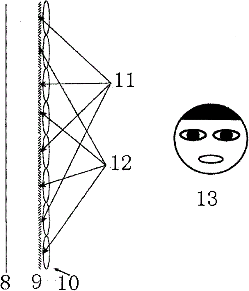
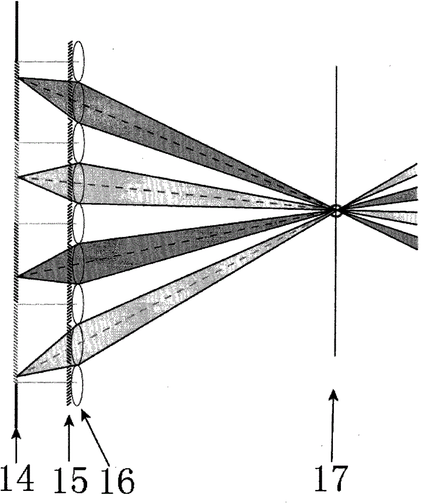
[0022] Such as figure 2 and image 3 As shown, in order to achieve the above object, the present invention provides a wide viewing angle integrated imaging three-dimensional display system, including: orthogonal polarization display device 8, polarizer array 9 and microlens array 10, polarizer array 9 is placed in parallel on the orthogonal In front of the polarized display device 8, the microlens array 10 is closely placed behind the polarizer array 9, and the microunit polarizer 15 is aligned with the microunit lens 16; The unit image arrays are superimposed and displayed in different polarization states, and the light of the displayed image is filtered by the polarizer array 9 and reaches the microlens array 10 , and the three-dimensional image 13 is displayed after being optically transformed by the microlens array 10 .

[0023] The orthogonally polarized display device 8 is used to display the micro-unit image array 14. It must be able to simultaneously display linearly...

Embodiment 2

[0026] The idea of ​​the present invention is to realize an integrated imaging display system with improved resolution and viewing angle by using orthogonal polarization display device, polarizer array and lens array.

[0027] Such as Figure 5 As shown, the orthogonally polarized display device 22 in this embodiment adopts a rear-projection dual-projector system, which includes two projectors No. No. polarizer 21, projection screen 23 capable of maintaining light polarization properties, but the present invention is not limited to the use of projection display equipment.

[0028] The specific implementation steps of this embodiment are as follows:

[0029] (1) Use two models, No. 1 projector 18 and No. 2 projector 19 with the same parameters, and a rear-projection projection screen 23 capable of maintaining light polarization characteristics as the orthogonal polarization display device 22 .

[0030] 1a) No. 1 projector 18 and No. 2 projector 19 are placed in parallel, and ...


PUM


Abstract

The invention provides a wide viewing angle integrated imaging three-dimensional display system which comprises a cross-polarization display device, a polarizer array and a microlens array. The polarizer array is arranged in front of the cross-polarization display device in parallel, the microlens array is arranged behind the polarizer array in a tight attaching mode, and unit polarizers and unit microlenses are aligned. Two frames of unit image arrays corresponding to different unit microlenses are displayed in an overlapping mode in different polarization states by the cross-polarization display device, light rays displaying images are filtered by the polarizer array and then arrive at the microlens array, optical transformation is conducted on the light rays through the microlens array, and then a three-dimensional image is displayed. According to the wide viewing angle integrated imaging three-dimensional display system, due to the fact that the polarizers are coupled with the unit microlens array, the display range and the resolution ratio of each micro unit image corresponding to each microlens are enlarged, and the watching angle of the three-dimensional display system is enlarged. The wide viewing angle integrated imaging three-dimensional display system improves display brightness, the complex degree for controlling the system and the manufacturing difficulty are lowered to a great extent, and the reliability of the system is improved.

Description

technical field [0001] The invention relates to a three-dimensional display technology, in particular to an integrated imaging three-dimensional display system with a wide viewing angle, which can be used in the fields of radio and television, movies, virtual reality and the like. Background technique [0002] Integrated imaging 3D display technology is a naked-eye stereoscopic display technology. Traditional integrated imaging 3D display includes two main links: acquisition and reconstruction. figure 1 shown. In the acquisition process of 3D scene information 1, a microlens array 2 composed of many lens units neatly arranged is used to collect stereoscopic information of 3D space objects and recorded through the recording medium at the rear end of the lens array. Since each lens unit acquires its own image information—unit image—from different directions, finally, all the unit images are neatly arranged to form a unit image array, which is recorded on the recording device ...

Claims


Application Information

Patent Timeline
Patent Type & Authority Patents(China)
IPC IPC(8): H04N13/00H04N13/04G02B27/22
Inventor 王晓蕊于硕刘鑫张建磊董维科刘德连
Owner XIDIAN UNIV
Features
  • R&D
  • Intellectual Property
  • Life Sciences
  • Materials
  • Tech Scout
  • Unparalleled Data Quality
  • Higher Quality Content
  • 60% Fewer Hallucinations
Learn More