
Zonal cut resistant glove

A cutting-resistant and glove-resistant technology, applied in the field of gloves, can solve problems such as waste and expensive yarn

Inactive Publication Date: 2014-10-29
ANSELL
View PDF12 Cites 6 Cited by
  • Summary
  • Abstract
  • Description
  • Claims
  • Application Information

AI Technical Summary

Problems solved by technology

Also, engineered yarn is expensive and it's a waste to weave it in areas of the glove that don't need it
Regardless, designing gloves for such applications can prove challenging in terms of considering the balance of properties, and previous attempts to provide such gloves have failed

Method used


Image

  • Zonal cut resistant glove
  • Zonal cut resistant glove
  • Zonal cut resistant glove

Examples


Embodiment Construction

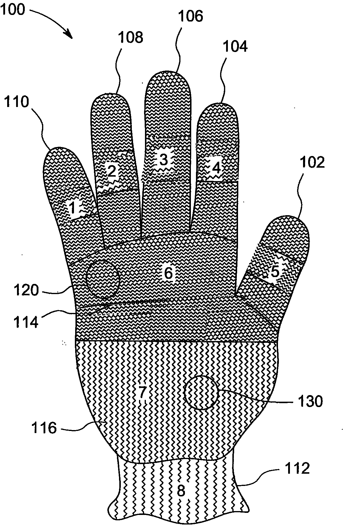
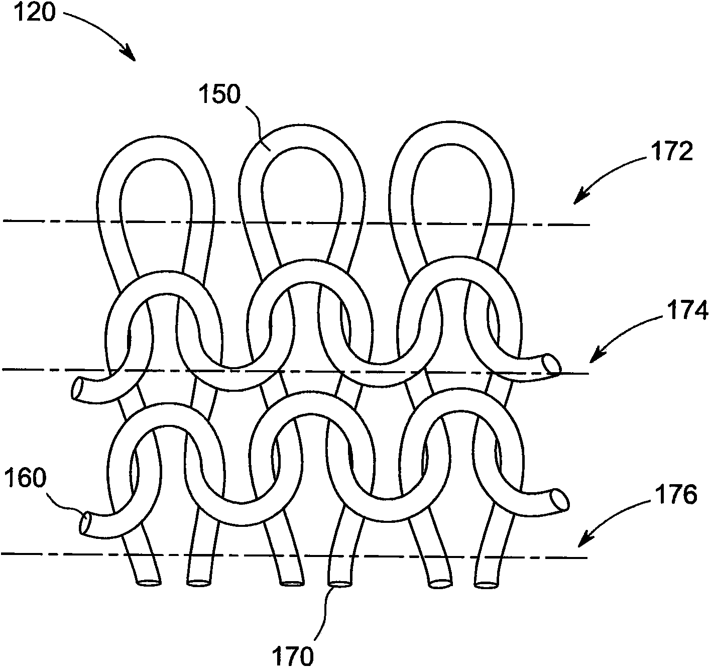
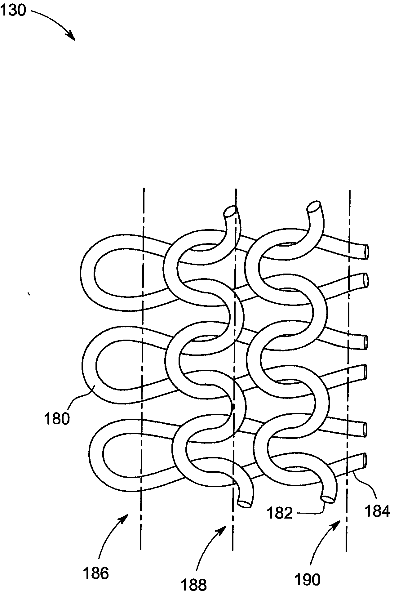
[0015] Embodiments of the present invention include a knit liner having at least one knit region. Alternatively, many knit liners include multiple regions. In some embodiments of the invention, at least one zone includes a vertically knitted thread path and includes a cut-resistant yarn. Also, some liners include regions with a second yarn exhibiting a second desired property (eg, flexibility, abrasion resistance, heat resistance, moisture management, etc.). In some embodiments of the present invention, in one or more regions of the liner, the second yarn is woven together with the main yarn, thereby creating a second layer of yarns in the one or more regions, the second Layer yarns may also include vertically knitted wire gauges. The area of ​​the inner liner, eg, knitted with cut-resistant yarn, may be defined by the end use of the glove.

[0016] The liner may be knitted by conventional knitting techniques, generally having a knitting thread gauge disposed horizontally w...


PUM


Abstract

Embodiments of the invention include knitted gloves having a cut-resistant yarn in at least one knitted zone of a glove and further including one or more yarns knitted into other knitted zones of the glove in which at least one zone has vertically knitted courses.

Description

technical field [0001] Embodiments of the present invention relate generally to gloves and, more particularly, to gloves that include cut-resistant yarns and fibers in selected regions. Background technique [0002] Gloves are used in many industries and households to protect the user's hands. Many gloves are designed for specific applications, for example, cut-resistant gloves for the food service industry. Cut resistant yarns are also used in gloves used in other industries such as workers using power tools, saw blades, working with metal pieces on the job, etc. However, many of these gloves are over-engineered, eg, cut-resistant yarns are knitted throughout the glove, although not all areas of the glove require cut resistance. In addition, cut-resistant yarns are generally more bulky and inflexible, producing gloves that are not thin, dexterous, flexible, or comfortable enough for a given application. Also, gloves often require resistance to chemicals, heat, flame, abr...

Claims


Application Information

Patent Timeline
Patent Type & Authority Applications(China)
IPC IPC(8): A41D19/00A41D19/015D04B1/28
CPCD04B1/28A41D19/01505D10B2403/0114
Inventor 詹姆士·H·茂兰德埃里克·汤普森阿古斯汀·泡蒂罗莫卡多杰勒德·罗德里古兹加雷里基·查尔斯·卡德诺伯特·赫克托·派若莱斯索利斯贾米·阿什沃斯约翰·法利·迈彻乐特雷蒙德·W·贝内特莎伦·A·奎恩
Owner ANSELL
Learn More