Novel roll booster ignition circuit

An ignition circuit and booster technology, applied to jet propulsion devices, machines/engines, gas turbine devices, etc., can solve problems such as failure to meet overall combat indicators, low reliability, and heavy cables, and reduce unexpected ignition accidents , Eliminate potential safety hazards, good safety performance

Active Publication Date: 2014-12-10
JIANGXI HONGDU AVIATION IND GRP
View PDF5 Cites 4 Cited by
  • Summary
  • Abstract
  • Description
  • Claims
  • Application Information

AI Technical Summary

Problems solved by technology

At present, the booster ignition mode is relatively simple and the safety is poor. Usually, the launch button is connected in series to the main line of the ignition circuit, and is realized by simple relay logic; The distance is as high as 130m. Even if a 4mm2 wire is used, the minimum ignition current of the booster cannot be satisfied through theoretical calculations. Just by increasing the cross-sectional area of ​​the wire, it is easy to cause the disadvantages of bulky cables, long laying time, and low reliability, which cannot meet the overall combat requirements. index

Method used


Image

  • Novel roll booster ignition circuit
  • Novel roll booster ignition circuit

Examples


Embodiment Construction

[0014] The present invention is described in detail below through the following specific examples.

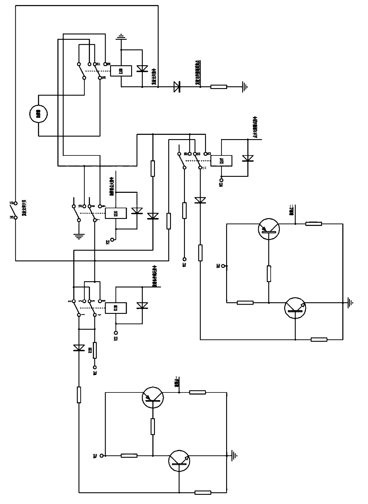
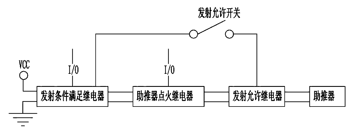
[0015] see figure 1 , figure 2 A new type of booster ignition circuit, including the common contact 1 of the relay that meets the emission conditions, the normally closed contact 2 of the relay that meets the emission conditions, the normally open contact 3 of the relay that meets the emission conditions, and the power switch of the relay that meets the emission conditions Common contact 4, the launch condition meets the normally closed contact of the relay power switch 5, the launch condition meets the normally open contact of the relay power switch 6, the common contact of the booster ignition relay 7, the normally closed contact of the booster ignition relay Contact 8, normally open contact of booster ignition relay 9, normally open contact 10 of booster ignition relay power switch, common contact 11 of ignition circuit detection relay, normally closed contact 12 of igniti...


PUM


Abstract

The invention discloses a novel roll booster ignition circuit. In the novel roll booster ignition circuit, a launch condition meeting relay is respectively connected with a roll booster ignition relay and one end of a launch allowing switch; the roll booster ignition relay and the other end of the launch allowing switch are respectively connected with a launch allowing relay; the launch allowing relay is connected with a roll booster; an ignition direction circuit comprises a detection pint, an ignition circuit detection relay and a detection circuit; the ignition circuit detection relay is respectively connected with the launch condition meeting relay, a launch condition allowing relay and the roll booster ignition relay; the front ends of the launch condition meeting relay and the roll booster ignition relay are provided with detection points. According to the novel roll booster ignition circuit, the output of the detection pints can be read by controlling the on and off operation of the ignition circuit detection relay, potential safety hazards are effectively eliminated, and the fight indexes can be met wholly.

Description

technical field [0001] The invention relates to the technical field of aircraft booster ignition, in particular to a novel booster ignition circuit. Background technique [0002] When the aircraft is launched on the ground, it is generally necessary to use the booster to obtain the initial speed of the aircraft. At the same time, in order to ensure the safe and reliable launch of the aircraft, the launch control system of the aircraft needs to accurately control the ignition of the booster. Therefore, the booster is required in the actual launch. The ignition circuit has high safety. At present, the booster ignition mode is relatively simple and the safety is poor. Usually, the launch button is connected in series to the main line of the ignition circuit, and is realized by simple relay logic; The distance is as high as 130m. Even if a 4mm2 wire is used, the minimum ignition current of the booster cannot be satisfied through theoretical calculations. Just by increasing the ...

Claims


Application Information

Patent Timeline
Patent Type & Authority Applications(China)
IPC IPC(8): F02C7/266
Inventor 郝传海王凡潘新平陶存炳陈佳峰莫耀奇鞠文飞许春雷汤新颖闫君丹
Owner JIANGXI HONGDU AVIATION IND GRP
Why Eureka
Try Eureka