Annular glass surrounded glass-blown miniature hemispherical resonant gyroscope and manufacturing method thereof

A technology of hemispherical resonant gyroscope and glass, which is applied in the direction of steering sensing equipment, etc., can solve the problems of restricting the development and application of micro hemispherical resonant gyroscope, and the low level of micromachining technology, and achieve the effect of high rigidity, good impact resistance and low cost

Active Publication Date: 2014-12-10
SHANGHAI JIAO TONG UNIV
View PDF8 Cites 9 Cited by
  • Summary
  • Abstract
  • Description
  • Claims
  • Application Information

AI Technical Summary

Problems solved by technology

[0004] However, due to the low level of micro-machining technology in our country, this limits the development and application of micro-hemispherical resonant gyroscopes in our country to a certain extent.

Method used


Image

  • Annular glass surrounded glass-blown miniature hemispherical resonant gyroscope and manufacturing method thereof
  • Annular glass surrounded glass-blown miniature hemispherical resonant gyroscope and manufacturing method thereof
  • Annular glass surrounded glass-blown miniature hemispherical resonant gyroscope and manufacturing method thereof

Examples


Embodiment 1

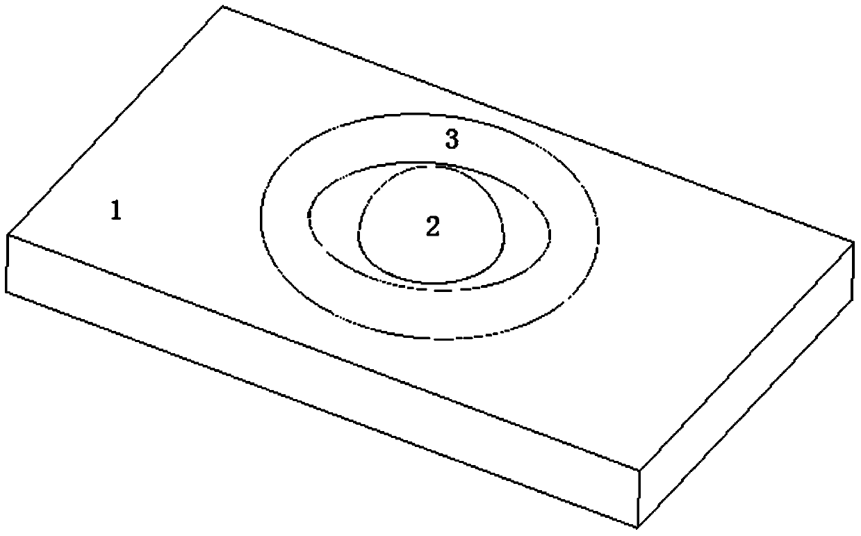
[0037] like Figure 1-2 As shown, the present embodiment provides a ring-shaped glass-enclosed glass-blown micro-hemispherical resonator gyroscope, including:

[0038] A cuboid silicon substrate 1;

[0039] A hemispherical shell-type central harmonic oscillator 2;

[0040] Eight metal electrodes made on the ring-shaped glass shell 3, including four driving electrodes and four detecting electrodes, are connected to pin 10 through leads; the four driving electrodes are not in contact with the hemispherical shell-type central resonator 2 , the four detection electrodes are not in contact with the hemispherical shell-type central resonator 2, and the spatial positions of the four driving electrodes and the spatial positions of the four detection electrodes are sequentially distributed at intervals;

[0041] Both the hemispherical shell-type central resonator 2 and the ring-shaped glass shell 3 are formed by glass blowing. The hemispherical shell-type central resonator 2 is locat...

Embodiment 2

[0044] like Figure 3(a) ~ Figure 3(f) , the present embodiment provides a method for manufacturing an annular glass-enclosed glass-blown micro-hemispherical resonator gyroscope, comprising the following steps:

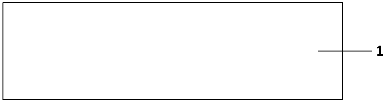
[0045] In the first step, as shown in FIG. 3(a), the single crystal cuboid silicon substrate 1 is cleaned;

[0046] In the second step, as shown in FIG. 3(b), the rectangular parallelepiped silicon substrate 1 is coated with glue, photolithography and developed to obtain a photoresist 6;

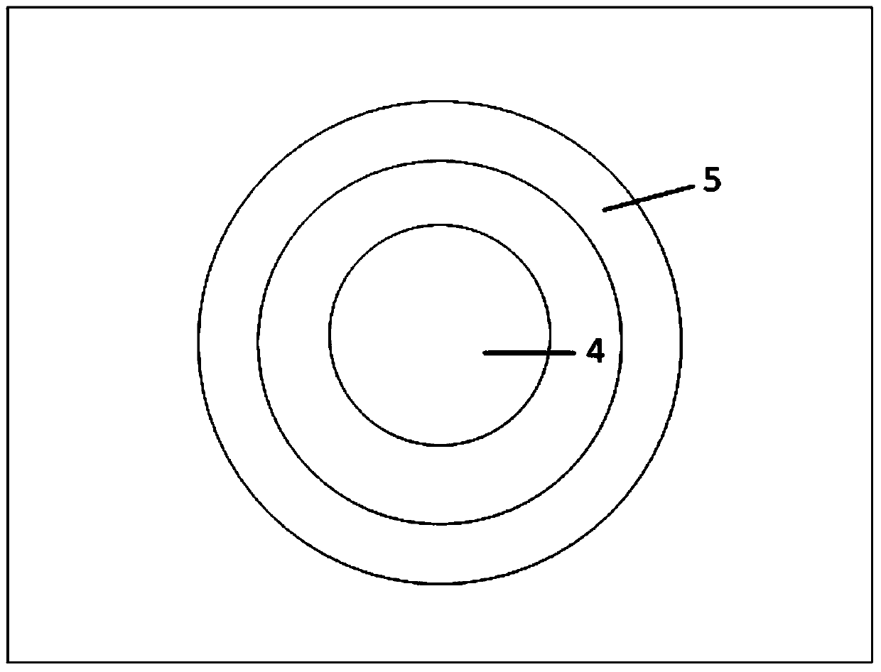
[0047] The third step, as shown in Figure 3(c), is to carry out ICP etching to the rectangular parallelepiped silicon substrate 1, and obtain a central circular groove 4 and a peripheral annular groove 5 after deglue, wherein, the peripheral annular groove 5 surrounds the central Circular groove 4 a week, and the outer edge 11 of central circular groove 4 and the inner edge of peripheral annular groove 5 keep a certain distance interval;

[0048] In the fourth step, as shown in FIG....


PUM


Abstract

The invention provides an annular glass surrounded glass-blown miniature hemispherical resonant gyroscope and a manufacturing method thereof. The gyroscope comprises a cuboidal silicon base, a hemispherical shell type central resonator, an annular glass shell and eight metal electrodes formed on annular glass, wherein the eight electrodes are uniformly distributed around the central resonator, consist of four drive electrodes and four detection electrodes and are connected to pins through leads; the drive electrodes and the detection electrodes can achieve electrostatic drive and detection through applying positive and negative voltage to corresponding pins; the hemispherical shell type central resonator and peripheral annular glass are manufactured by adopting a glass blowing process. The gyroscope adopts an MEMS (Micro-Electromechanical Systems) process for processing, is simple in structure, small in volume and relatively high in accuracy, and has great development prospects.

Description

technical field [0001] The invention relates to a solid wave mode matching gyroscope in the field of micro-electromechanical technology, in particular to a ring-shaped glass-enclosed glass-blown micro hemispherical resonant gyroscope and a preparation method thereof. Background technique [0002] Gyroscope is an inertial device that can be sensitive to the angle or angular velocity of the carrier, and it plays a very important role in the fields of attitude control, navigation and positioning. With the development of national defense technology and aviation and aerospace industries, the requirements of inertial navigation systems for gyroscopes are also developing in the direction of low cost, small size, high precision, multi-axis detection, high reliability, and adaptability to various harsh environments. The micro gyroscope based on MEMS technology is processed by batch manufacturing technology, its cost, size, and power consumption are very low, and its environmental ada...

Claims


Application Information

Patent Timeline
Patent Type & Authority Applications(China)
IPC IPC(8): G01C19/56
CPCG01C19/56
Inventor 张卫平刘亚东唐健汪濙海成宇翔孙殿竣陈文元
Owner SHANGHAI JIAO TONG UNIV
Why Eureka
Try Eureka