High-temperature resistant vibration tool for horizontal well

A vibrating tool and high-temperature-resistant technology, which is applied to vibration generating devices, wellbore/well components, earthwork drilling and production, etc., can solve problems such as failure to complete drilling operations, self-locking of coiled tubing, and inclusion of rubber parts, etc. Displacement operation, improve work reliability, and avoid the effect of mechanical transmission

Active Publication Date: 2014-12-24
JEREH ENERGY SERVICES
View PDF7 Cites 102 Cited by
  • Summary
  • Abstract
  • Description
  • Claims
  • Application Information

AI Technical Summary

Problems solved by technology

However, limited by the coiled tubing itself, the coiled tubing is prone to self-locking in large horizontal wells, causing the coiled tubing to fail to reach the predetermined depth for related operations, or to fail to apply sufficient drilling pressure after reaching the designated position, resulting in failure of the coiled tubing operation. Unable to successfully complete relevant drilling operations
The published patent "Vibration Tool for Extended Reach Well" Patent No.: CN 202673216U, although the torque friction of the drill pipe has been reduced, which is beneficial to the construction of underground operations, but th

Method used


Image

  • High-temperature resistant vibration tool for horizontal well
  • High-temperature resistant vibration tool for horizontal well
  • High-temperature resistant vibration tool for horizontal well

Examples


Embodiment Construction

[0025] The principles and features of the present invention are described below in conjunction with the accompanying drawings, and the examples given are only used to explain the present invention, and are not intended to limit the scope of the present invention.

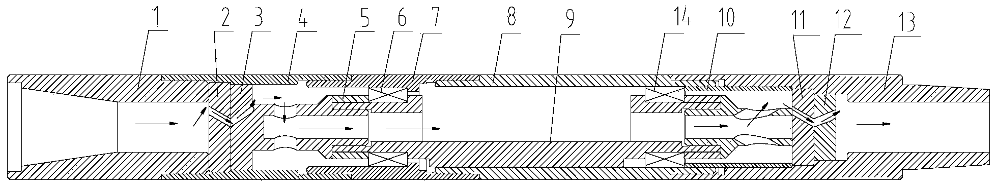
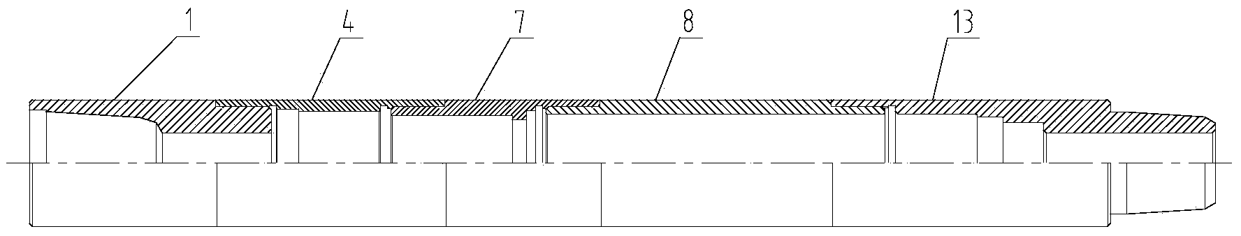
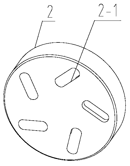
[0026] Such as Figure 1 to Figure 6 As shown, a high-temperature-resistant vibration tool for horizontal wells includes a housing assembly and a vibration assembly located inside the housing assembly:

[0027] The shell assembly includes an upper joint 1, an upper joint sleeve 4, a connecting sleeve 7, an outer sleeve 8 and a lower joint 13 which are sequentially socketed from top to bottom; the vibration assembly includes an upper turbine 3, which is sequentially connected from top to bottom. The eccentric shaft 9 and the lower end turbine 11, the vibration assembly is installed in the housing assembly through the upper end bearing 6 and the lower end bearing 14, and the upper end bearing 6 and the lower end beari...


PUM


Abstract

The invention relates to a high-temperature resistant vibration tool for a horizontal well. The high-temperature resistant vibration tool for the horizontal well comprises a shell assembly and a vibration assembly arranged in the shell assembly and is characterized in that the shell assembly comprises an upper joint, an upper joint sleeve, a connection sleeve, a cover and a lower joint which sleeve from top to bottom in sequence; the vibration assembly comprises an upper end turbine, an eccentric shaft and a lower end turbine which are connected in sequence from top to bottom; the vibration assembly is arranged in the shell assembly by an upper end bearing and a lower end bearing; the upper end bearing and the lower end bearing respectively sleeve two end shafts of the eccentric shaft; an upper thrust ring and a lower thrust ring are respectively arranged at two ends of the vibration assembly and are respectively arranged in the upper joint sleeve and the lower joint; a channel for allowing fluid to flow is arranged in each of the shell assembly and the vibration assembly. The high-temperature resistant vibration tool for the horizontal well has the beneficial effects that the work reliability and high temperature resistance of the tool are improved, the deepening depth is increased, and enough drilling and pressing effects are applied.

Description

technical field [0001] The invention relates to the technical field of oil and gas extraction tools, in particular to a high-temperature-resistant vibration tool for horizontal wells. Background technique [0002] With the rapid development of shale gas, the number of horizontal wells is increasing day by day. Compared with traditional drill pipe operations, coiled tubing can perform operations such as drilling bridge plugs and workover without snubbing. However, limited by the coiled tubing itself, the coiled tubing is prone to self-locking in large horizontal wells, causing the coiled tubing to fail to reach the predetermined depth for related operations, or to fail to apply sufficient drilling pressure after reaching the designated position, resulting in failure of the coiled tubing operation. Unable to successfully complete related drilling operations. The published patent "Vibration Tool for Extended Reach Well" Patent No.: CN 202673216U, although the torque friction ...

Claims


Application Information

Patent Timeline
IPC IPC(8): E21B28/00
Inventor 孟凡超韩滔张博浩
Owner JEREH ENERGY SERVICES
Why Eureka
Try Eureka