Quadric curve voltage-adjustment gain equalization circuit

A technology of gain equalization and quadratic curve, which is applied in the field of communication, can solve the problems of unbalanced parabolic gain curve, practicability that cannot meet power amplifier products, and complicated implementation methods, and achieves flexible and convenient application forms, good practicability and cost advantages , the effect of simple structure

Active Publication Date: 2014-12-24
COMBA TELECOM SYST CHINA LTD
View PDF6 Cites 10 Cited by
  • Summary
  • Abstract
  • Description
  • Claims
  • Application Information

AI Technical Summary

Problems solved by technology

[0004] Existing gain equalization technologies can be divided into three categories: (1) primary curve gain equalizers, this type of equalizer can only equalize positive slope or negative slope linear gain curves, all of which belong to primary curves, and cannot equalize parabolic gain curves; (2) quadratic curve gain equalizer, this type of equalizer can equalize the parabolic gain curve, but the implementation mode of the quadratic curve gain equalizer in the prior art is more complicated, and the practicability cannot meet the requirements of power amplifier products; (3) Digital gain equalizer, in theory, this type of equalizer can equalize the gain curve of any shape, use the computing power of digital chips such as single chip microcomputer or FPGA, perform equalization processing in the digital domain, and then convert the frequency from intermediate frequency to radio frequency, but digital gain equalizer can only Applied in products with strong digital computing resources and frequency conversion functions, the scope of application is small

Method used


Image

  • Quadric curve voltage-adjustment gain equalization circuit
  • Quadric curve voltage-adjustment gain equalization circuit
  • Quadric curve voltage-adjustment gain equalization circuit

Examples


Embodiment Construction

[0022] The content of the present invention will be further elaborated below in conjunction with specific embodiments.

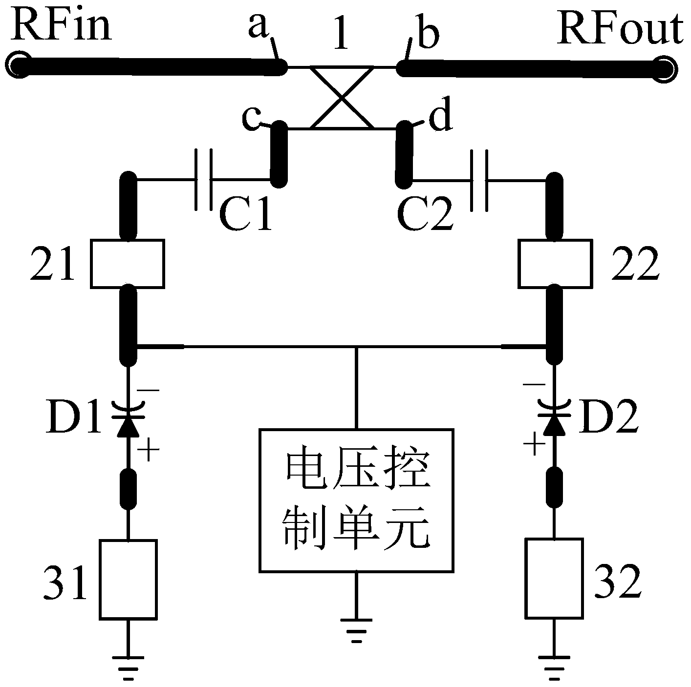
[0023] Such as figure 2 As shown, a quadratic electric gain equalization circuit includes a 3dB bridge 1, a first attenuation unit 21, a second attenuation unit 22, varactor diodes D1, D2, a first resonant circuit 31, and a second resonant circuit 32 , capacitors C1, C2, voltage control unit.

[0024] The 3dB electric bridge has 4 ports, as shown in the figure, they are a, b, c, and d respectively, among which port a is the input port, port b is the junction port, port c is the first output port, and port d is the second output port After the RF input signal is input from port a, two signals with equal amplitude and 90° phase difference are generated from ports c and d.

[0025] The first output port c and the second output port d of the 3dB electric bridge 1 are respectively connected to the first attenuation unit 21 and the second attenuation unit 22; t...


PUM


Abstract

The invention provides a quadric curve voltage-adjustment gain equalization circuit. The quadric curve voltage-adjustment gain equalization circuit comprises a 3dB bridge, a first attenuation unit, a second attenuation unit, varactors D1and D2, a first resonance circuit, a second resonance circuit, a capacitor C1, a capacitor C2 and a voltage control unit, wherein a first output port and a second output port of the 3dB bridge are connected with the first attenuation unit and the second attenuation unit respectively, the capacitor C1 is arranged between the first output port of the 3dB bridge and the first attenuation unit, the capacitor C2 is arranged between the second output port and the second attenuation unit, or the capacitor C1 is arranged at an input port and the capacitor C2 is arranged at a joint port; the negative electrode of the varactor D1 is connected with the first attenuation unit, and the positive electrode of the varactor D1 is connected with the first resonance circuit; the negative electrode of the varactor D2 is connected with the second attenuation unit, and the positive electrode of the varactor D2 is connected with the second resonance circuit; the other end of the first resonance circuit and the other end of the second resonance circuit are both grounded; one end of the voltage control unit is connected with the negative electrode of the varactor D1 and the negative electrode of the varactor D2, and the other end of the voltage control unit is grounded. The quadric curve voltage-adjustment gain equalization circuit can realize voltage-adjustment equalization of a quadric gain curve.

Description

【Technical field】 [0001] The invention relates to the technical field of communication, in particular to a quadratic curve electric adjustment gain equalization circuit. 【Background technique】 [0002] In the mobile communication network, the typical gain curve of the power amplifier (hereinafter referred to as the power amplifier) ​​is as follows figure 1 As shown, it is a convex curve. The driving stage and the final stage of the power amplifier usually use LDMOS (laterally diffused metal oxide semiconductor) power amplifier tubes. The input and output impedances of LDMOS power amplifier tubes usually change with frequency. The gain in f2 is relatively large, and the gain curve is parabolic (that is, a quadratic curve), and the gain reaches the maximum value near the center frequency point f0. [0003] The parabolic gain curve of the power amplifier will have many adverse effects on the communication system, mainly deteriorating the linearity index and efficiency index o...

Claims


Application Information

Patent Timeline
Patent Type & Authority Applications(China)
IPC IPC(8): H03G3/20
Inventor 査文清李合理张磊
Owner COMBA TELECOM SYST CHINA LTD
Why Eureka
Try Eureka