A circuit-controlled worm machining mechanism

A technology of processing mechanism and circuit control, applied in the direction of worm, mechanical equipment, components with teeth, etc., can solve the trouble of worm gear tooth shape, difficult to meet the cost reduction, improve the processing speed and accuracy, and difficult to ensure the accuracy of the tooth groove shape and position. And other issues

Inactive Publication Date: 2016-07-13
国网山东省电力公司沂源县供电公司
View PDF6 Cites 0 Cited by
  • Summary
  • Abstract
  • Description
  • Claims
  • Application Information

AI Technical Summary

Problems solved by technology

4. The efficiency of worm transmission is low, and it is generally believed that the efficiency of worm transmission is lower than that of gear transmission
However, the shape processing and manufacturing of the worm gear tooth profile is troublesome, and it is difficult to ensure the accuracy of the processed tooth groove shape and position
[0003] In particular, in some specific application areas, such as soft materials (such as plastics) processing, traditional metal processing methods will be difficult to meet the requirements of reducing costs and improving processing speed and accuracy

Method used


Image

  • A circuit-controlled worm machining mechanism
  • A circuit-controlled worm machining mechanism
  • A circuit-controlled worm machining mechanism

Examples


Embodiment Construction

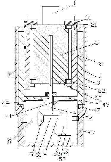
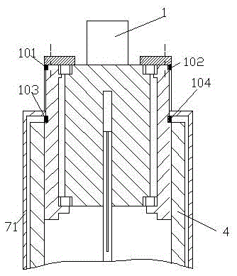
[0014] Attached below Figure 1-3 , the present invention will be described in detail.

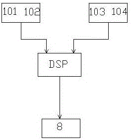
[0015] A circuit-controlled worm processing mechanism for processing a blank 1 into a worm, the processing mechanism includes a DSP control circuit, a blank carrier 2, a sleeve 3 with external threads, and a drive sleeve 4 with internal threads And the frame 7, the blank carrier 2 is used to carry the blank 1, the upper end and the lower end of the blank carrier 2 are axially relative to the sleeve 3 with external thread through an upper bearing 21 and a lower bearing 22 respectively. Fixedly installed in the sleeve 3 with external thread, the sleeve 3 with external thread is screwed into the drive sleeve 4 with internal thread, the drive sleeve 4 with internal thread The lower end is rotatably mounted on the frame 7 through the thrust bearing 47, and the inside of the frame 7 has a chamber 72, and in the chamber 72, a driving motor 8 is fixed on the left inner wall of the chamber of the ...


PUM


Abstract

The invention discloses a worm processing mechanism controlled by a circuit. The worm processing mechanism is used for processing a blank piece (1) into a worm and comprises a DSP (Digital Signal Processing) control circuit, a blank-piece bearing piece (2), a sleeve (3) with external threads, a driving sleeve (4) with internal threads and a rack (7), wherein the blank-piece bearing piece (2) is used for bearing the blank piece (1); relative to the sleeve (3) with the external threads, the upper end and the lower end of the blank-piece bearing piece (2) are respectively and fixedly arranged in the sleeve (3) with the external threads by an upper bearing (21) and a lower bearing (22) in an axial manner; the sleeve (3) with the external threads is matched in the driving sleeve (4) with the internal threads by threads.

Description

technical field [0001] The present application relates to the field of worm machining, in particular to a circuit-controlled worm machining mechanism. Background technique [0002] The worm drive is composed of a worm and a worm gear, and the worm is generally the active part. Worms, like threads, can be divided into right-handed and left-handed. Worm drive has the following advantages: 1. Large transmission ratio and compact structure. The number of worm heads is represented by Z1 (generally Z1=1~4), and the number of worm gear teeth is represented by Z2. It can be seen from the transmission ratio formula I=Z2 / Z1 that when Z1=1, that is, the worm is single-headed, and the worm must turn Z2 to turn the worm wheel for one turn, so a large transmission ratio can be obtained. Generally, in power transmission, take The transmission ratio I=10-80; in the indexing mechanism, I can reach 1000. Such a large transmission, such as gear transmission, needs to adopt multi-stage tran...

Claims


Application Information

Patent Timeline
Patent Type & Authority Patents(China)
IPC IPC(8): B23F13/00
Inventor 李锋伊波白波李汝军庄彬
Owner 国网山东省电力公司沂源县供电公司
Why Eureka
Try Eureka