Power grid safety supervision detection device based on intelligent electric meter

A technology of smart meter and detection device, applied in the direction of measurement device, measurement of electricity, measurement of electricity variables, etc., can solve the problems of complex circuit, high price, single function, etc., to reduce losses, facilitate monitoring, and reduce the cost of preventing electricity theft. Effect

CN104422834AInactive Publication Date: 2015-03-18河南单点留学中介服务有限公司
0 Cites 9 Cited by

Patent Information

Authority / Receiving Office
CN · China
Patent Type
Applications(China)
Current Assignee / Owner
Publication Date
2015-03-18
Estimated Expiration
Not applicable · inactive patent

Smart Images

  • Figure 1
    Figure 1
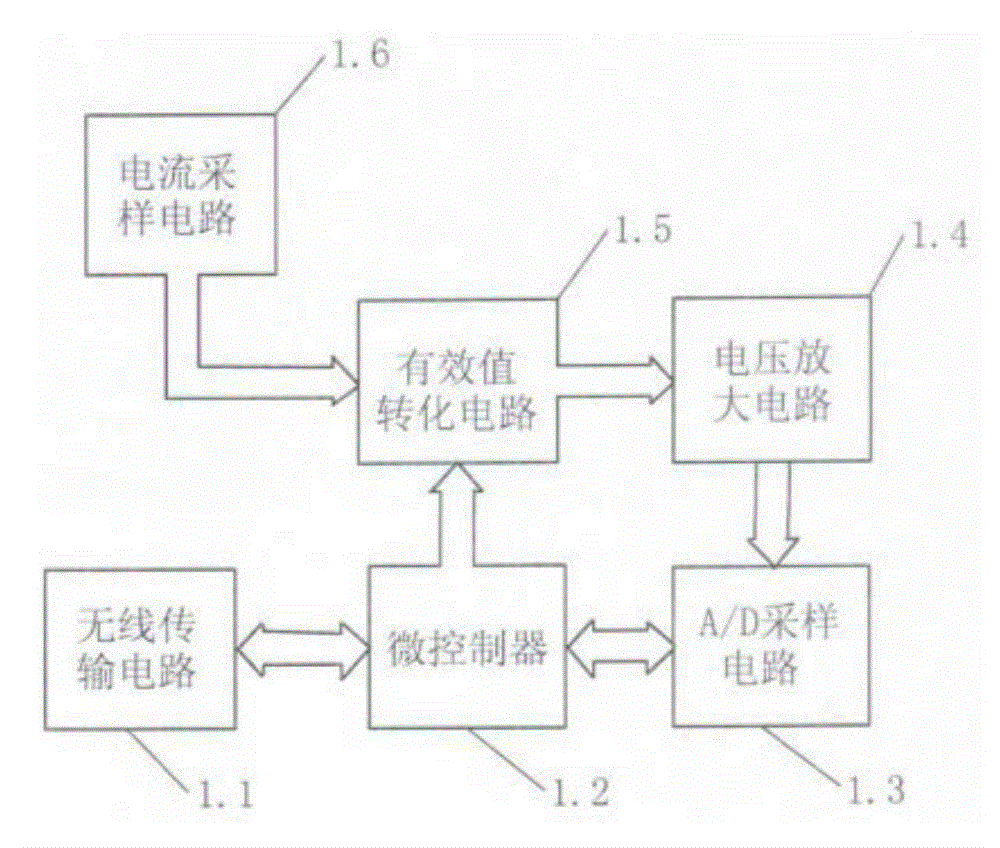
  • Figure 2
    Figure 2
  • Figure 3
    Figure 3
Patent Text Reader

Abstract

The invention relates to the technical field of power grid safety supervision protection, in particular to a power grid safety supervision detection device based on an intelligent electric meter. According to the power grid safety supervision detection device, a current wireless acquisition module is communicated with an intelligent electric meter module by a Bisbee network transmission device and is in signal communication with an inspection monitoring computer by a GPRS / CDMA (General Packet Radio Service / Code Division Multiple Access) network transmission device; a current wireless acquisition circuit is internally provided with a meter-front current detection module circuit; the intelligent electric meter module is internally provided with an intelligent electric meter module circuit. According to the power grid safety supervision detection device based on the intelligent electric meter, an anti-electricity-stealing inspection monitoring device can be used for effectively preventing illegal electricity stealing phenomena from occurring, and the loss of power supply departments is reduced; the power grid safety supervision detection device has data remote transmission and networked management functions and is convenient for monitoring; the anti-electricity-stealing cost of the power supply departments can be reduced, the intelligent anti-electricity-stealing management level is improved, and the power grid safety supervision detection device is suitable for being applied to the power utilization management of the electric power departments.
Need to check novelty before this filing date? Find Prior Art

Description

technical field

[0001] The invention relates to the technical field of power grid safety monitoring and protection, in particular to a power grid safety monitoring detection device based on a smart meter. Background technique

[0002] With the continuous and rapid growth of our country's economy, industrial electricity consumption has increased significantly, and some enterprises have increased the phenomenon of stealing electricity year by year in order to seek illegal benefits and reduce production costs. Due to the large number of applications of electronic energy meters equipped with anti-stealing chips, the traditional method of stealing electricity by changing lines in the meter has been basically controlled, so some units have adopted a more bold method of stealing electricity, directly leading the wires in front of the meter Or cut off the external circuit of electric energy meter, promptly electric current does not pass through electric energy meter, electric energy...

Examples

Embodiment Construction

[0013] Attached below figure 1 ~ attached image 3 The present invention is described in detail below.

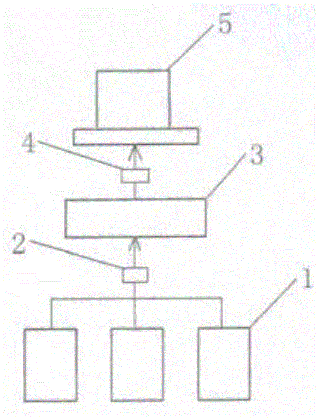
[0014] Such as figure 1 As shown, the current wireless acquisition module 1 of the present invention communicates with the smart meter module 3 through the Bisbee network transmitter 2, and communicates with the inspection and monitoring computer 5 through the GPRS / CDMA network transmitter 4.

[0015] A front-of-the-meter current detection module is installed in the current wireless acquisition module.

[0016] The circuit composition of the current detection module in front of the meter of the present invention:

[0017] Such as figure 2 As shown, the current sampling circuit 1.6 is successively connected with the effective value conversion circuit 1.5 and the voltage amplifying circuit 1.4, and the voltage amplifying circuit is connected with the A / D sampling circuit 1.3 and then connected with the microcontroller 1.2, and the microcontroller and the wireless transmi...