Lamp, reflector for lamp, and light unit for lamp

A technology of light source components and reflectors, which is applied in the field of lamps, reflectors for lamps and light source components for lamps, and can solve problems such as difficulty in conformity

Inactive Publication Date: 2015-04-29
KOITO ELECTRIC IND
View PDF12 Cites 2 Cited by
  • Summary
  • Abstract
  • Description
  • Claims
  • Application Information

AI Technical Summary

Problems solved by technology

In this case, two stages of control are required and

Method used


Image

  • Lamp, reflector for lamp, and light unit for lamp
  • Lamp, reflector for lamp, and light unit for lamp
  • Lamp, reflector for lamp, and light unit for lamp

Examples


Example

[0173] 2. The first embodiment

[0174] (1) The overall structure of the lamp

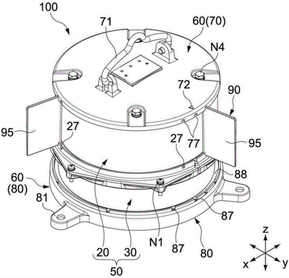
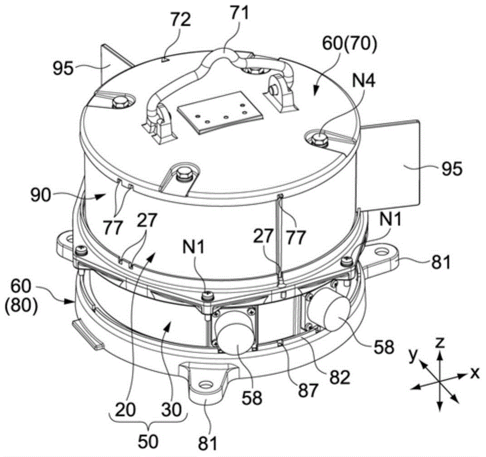
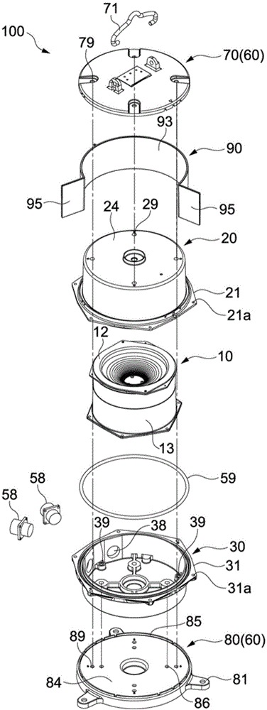
[0175] figure 1 It is a perspective view showing the front side of a single-type boat light as the light fixture according to the first embodiment of the present invention. figure 2 Is shown figure 1 A perspective view of the back side of the lamp device 100 shown. image 3 It is an exploded perspective view of the lamp 100. Lamp 100, in figure 1 Among them, the z direction is mainly used as the vertical direction (longitudinal direction). In addition, in the following description, the z direction is referred to as the vertical direction, and the x direction and the y direction are referred to as two axial directions orthogonal to the horizontal plane.

[0176] The lamp unit 100 includes: a light source assembly 10 (refer to image 3 ), a receiving body 50 accommodating the light source assembly 10, a shutter 90 installed on the receiving body 50 and defining the light emitting range of the lamp 100, an...

Example

[0242] 3. The second embodiment

[0243] Figure 14 It is a cross-sectional view showing the lamp device according to the second embodiment of the present invention. In the following description, the description of the same content of the components and functions included in the lamp device according to the first embodiment described above is abbreviated or omitted, and the difference is mainly described.

[0244] The lamp includes a light source assembly 110 that is different from the light source assembly 10 of the lamp according to the first embodiment. Figure 15 It is an exploded perspective view of the light source assembly 110. The inner cover 13 in the light source assembly 110 has the same structure as the inner cover 13 according to the first embodiment described above.

[0245] The light source mounted on the light source substrate 111 is an LED 15, and the LED 15 is arranged at the center of the light source substrate 111. The vertical axis through the position of the L...

Example

[0248] 4. The third embodiment

[0249] (1) The overall structure of the lamp

[0250] Figure 16 It is a perspective view showing a dual-type lamp device 300 according to the third embodiment of the present invention. Figure 17 Is showing Figure 16 A perspective view of the back side of the dual-type lamp device 300 shown. Figure 18 It is an exploded perspective view of the lamp 300. Figure 19 It is a cross-sectional view of the lamp 300. As the dual-type lamp device 300 according to the present embodiment, a starboard side lamp is taken as an example.

[0251] The dual-type lamp device 300 includes a first housing body 50A and a second housing body 50B connected to a lower portion of the first housing body 50A. In addition, the lamp 300 includes a cover 70 as one of the end members connected to the upper part of the first container 50A, a bottom 80 as one of the end members connected to the lower part of the second container 50B, and The shutters 90 (first shutter, second shu...


PUM


Abstract

The invention provides a lamp, a reflector for the lamp and a light unit for the lamp. Luminosity over a set value can be achieved in a prescribed limit of the peripheral direction and the shaft direction. The reflector (12) is provided with a base part (126), a top (122) and a reflecting part (124). The reflecting part (124) is provided with a curved face body (120) and annular convex face parts (121). The curved face body (120) is arranged between the base part (126) and the top (122) and is formed by rotation curves by centering the top (122). The annular convex face parts (121) are arranged on the curved face body (120) in a way of a concentric circle by centering the top 122. Via the light diffusing function of the annular convex face parts (121), deviation of the luminosity can be restrained and luminosity over the set value can be achieved in the described limit of the peripheral direction and the shaft direction.

Description

technical field [0001] The invention relates to a lamp, a reflector for the lamp and a light source assembly for the lamp used in the fields related to navigation or aviation. Background technique [0002] In order to ensure the safety of navigation and air traffic, according to laws and regulations, it is an obligation to install lamps on the hull and aircraft body. Detailed regulations. In recent years, lamps using, for example, light-emitting diodes as light sources have been proposed, and proposals related to technologies such as luminosity and light distribution of light-emitting diodes have been proposed. [0003] Patent Document 1 describes a ship light, which includes a light source and a pair of disk-shaped conical reflectors. Mirrors are arranged above and below the light source. In addition, the ship light has: a base assembly for accommodating a power circuit, a trunk tube for accommodating the above-mentioned light source and a reflector, and a top assembly f...

Claims


Application Information

Patent Timeline
IPC IPC(8): F21V7/09F21V19/00F21S8/00F21W101/04F21W101/06F21Y101/02F21W107/20F21W107/30
CPCF21S8/00F21V7/09F21V17/12F21V19/001F21W2107/20F21W2107/30F21S2/005F21V7/0066F21V7/0091F21K9/20F21K9/69F21Y2115/10
Inventor 小岛泰代药师寺慧服部启太柴崎航也田中典明古川贤志
Owner KOITO ELECTRIC IND
Why Eureka
Try Eureka