Check patentability & draft patents in minutes with Patsnap Eureka AI!

Deceleration strip on road

A technology of speed bumps and roads, applied in the field of new road speed bumps, can solve the problems of affecting the surrounding environment, vehicle loss, noise generation, etc., and achieve the effect of creating a harmonious living environment

Inactive Publication Date: 2015-05-20
XIANGYANG CITY XIANGZHOU DISTRICT NO 4 HIGH SCHOOL
View PDF0 Cites 0 Cited by
  • Summary
  • Abstract
  • Description
  • Claims
  • Application Information

AI Technical Summary

Problems solved by technology

Because no matter whether the vehicle is speeding or not, it must pass through the speed reduction belt, which will not only cause a certain degree of loss to the vehicle, but also generate noise and affect the surrounding environment.

Method used


Image

  • Deceleration strip on road

Examples


Embodiment Construction

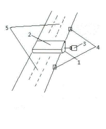
[0008] figure 1 Shown: rubber convex surface 1, the opposite side of the rubber convex surface 1 is the rubber plane 2, the side of the rubber plane 2 is the motor 3, there is a speed measuring device 4 near the motor 3, and the speed measuring device 4 is fixed on the side of the road 5.

[0009] During the specific implementation, the rubber plane 2 of the speed bump is usually laid on the road. Only when the speed measuring device 4 detects that the speed of the passing vehicle exceeds the rated speed, the motor 3 is automatically and quickly controlled to work, so that the rubber convex surface 1 of the speed bump is laid on the road. on the road.


PUM


Abstract

The invention provides a deceleration strip on a road. The deceleration strip comprises a rubber convex face and a rubber plane. When speed-detecting devices detect that the speed of a vehicle passing through the road exceeds a rated speed, the rubber convex face is automatically rapidly adjusted to be paved on the road. Under other conditions, the rubber plane is paved on the road. In this way, wear of the vehicle is reduced to a certain extent, the noise is also avoided possibly, and a harmonious living environment is created. Lots of adverse impacts are caused due to the fact that the traditional deceleration strip is fixed on the road in life. The advantages of the novel deceleration strip on the road outweigh the disadvantages.

Description

technical field [0001] The invention relates to a device for decelerating a vehicle on a road, in particular to a new road deceleration belt. Background technique [0002] On the road, speed bumps are often seen. The traditional speed bump is a kind of rubber fixed on the road. No matter whether the vehicle is overspeeding, it must pass through the speed bump, which will not only cause a certain degree of wear and tear to the vehicle, but also generate noise and affect the surrounding environment. SUMMARY OF THE INVENTION [0003] The purpose of the present invention is to provide a road speed bump that can create a harmonious living environment [0004] The technical scheme adopted in the present invention is as follows: the opposite side of the rubber convex surface is the rubber plane, the side of the rubber plane is the electric motor, the vicinity of the electric motor is the speed measuring device, and the speed measuring device is fixed on the side of the road. ...

Claims


Application Information

Patent Timeline
Patent Type & Authority Applications(China)
IPC IPC(8): E01F9/047E01F9/529
Inventor 徐若飞
Owner XIANGYANG CITY XIANGZHOU DISTRICT NO 4 HIGH SCHOOL
Features
  • R&D
  • Intellectual Property
  • Life Sciences
  • Materials
  • Tech Scout
  • Unparalleled Data Quality
  • Higher Quality Content
  • 60% Fewer Hallucinations
Learn More