Dosage modulation scanning method and device

A technology of dose modulation and scanning method, which is applied in the medical field, can solve the problem of unclear scanning images of a single tube exposure, and achieve the effect of improving quality

Active Publication Date: 2015-05-27
NEUSOFT MEDICAL SYST CO LTD
View PDF3 Cites 4 Cited by
  • Summary
  • Abstract
  • Description
  • Claims
  • Application Information

AI Technical Summary

Problems solved by technology

[0005] The present invention provides a dose modulation scanning method and device, which are used to solve the problem of unclear scanning images of a single tube exposure in the existing dose modulation scanning and improve the quality of scanning images

Method used


Image

  • Dosage modulation scanning method and device
  • Dosage modulation scanning method and device
  • Dosage modulation scanning method and device

Examples


Embodiment 1

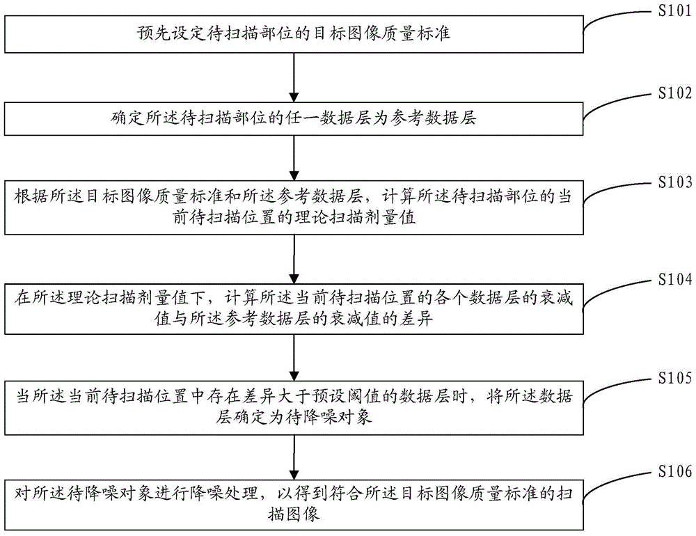
[0050] refer to figure 1 , figure 1 The flow chart of the dose modulation scanning method provided by the embodiment of the present invention, the method includes:

[0051] S101: Presetting a target image quality standard of a part to be scanned.

[0052] In this embodiment, before starting the dose modulation scanning method, a desired image quality standard, ie, a target image quality standard, is first set. The specific setting method or setting parameters are not limited, and the target image quality standard may be an expected image noise level, an expected image signal-to-noise ratio, or an expected dose level, etc.

[0053]Taking the target image quality standard as the image signal-to-noise ratio as an example, the setting range of the image signal-to-noise ratio may be 0.3-3.0. The parameter 1.0 means that the image signal-to-noise ratio of the current target image is equal to the standard image signal-to-noise ratio of the current scanning protocol. The so-called...

Embodiment 2

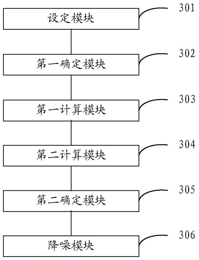
[0101] refer to image 3 , image 3 A schematic structural diagram of a dose modulation scanning device provided in this embodiment, the device includes:

[0102] The setting module 301 is used to pre-set the target image quality standard of the part to be scanned;

[0103] A first determining module 302, configured to determine any data layer of the part to be scanned as a reference data layer;

[0104] The first calculation module 303 is configured to calculate the theoretical scanning dose value of the current position to be scanned of the part to be scanned according to the target image quality standard and the reference data layer;

[0105] The second calculation module 304 is configured to calculate the difference between the attenuation value of each data layer at the current position to be scanned and the attenuation value of the reference data layer under the theoretical scanning dose value;

[0106] The second determination module 305 is configured to determine th...


PUM


Abstract

The embodiment of the invention discloses a dosage modulation scanning method and device. The method comprises the following steps: pre-setting a target image quality standard of a part to be scanned and determining any data layer of the part to be scanned as a reference data layer; calculating a theoretical scanning dosage value of the current part to be scanned according to the target image quality standard and the reference data layer; calculating the difference between an attenuation value of each data layer of the current part to be scanned and an attenuation value of the reference data layer; when a data layer with the difference larger than a pre-set threshold value exists in the current part to be scanned, determining the data layer as an object to be subjected to noise reduction treatment; and carrying out noise reduction treatment on the object to be subjected to the noise reduction treatment to obtain a scanning image meeting the target image quality standard. According to the dosage modulation scanning method and device, the object to be subjected to the noise reduction treatment is determined and is subjected to the noise reduction treatment so that the problem in existing dosage modulation scanning that a single-time bulb tube exposed scanning image is not clear is solved and the quality of the scanning image is improved.

Description

technical field [0001] The invention relates to the field of medical technology, in particular to a dose modulation scanning method and device. Background technique [0002] Dose modulation scanning refers to a scanning method in which the scanning dose changes continuously as the scanning position changes during the scanning process. The dose modulation scanning method is used for CT clinical scanning, and the purpose is to achieve the consistency of noise in each part to be scanned. [0003] However, due to the same scanning position, the exposure dose is a fixed value during one tube exposure. If the attenuation value of the Z-direction range corresponding to the current scanning position changes greatly during a single tube exposure in the dose modulation scan, it will lead to a significant difference in the noise of the current scan data, which violates the original design intention of the dose modulation scan . For example, when a single tube is exposed at the shoul...

Claims


Application Information

Patent Timeline
Patent Type & Authority Applications(China)
IPC IPC(8): A61B6/03
CPCA61B6/5205A61B6/5258A61B6/542A61B6/583G06T5/002G06T11/005G06T2207/10081G06T2207/20192
Inventor 楼珊珊逄岭
Owner NEUSOFT MEDICAL SYST CO LTD
Why Eureka
Try Eureka