A combined super-discharging energy-dissipating flood unit and method

A combined flood overflow technology, applied in water conservancy projects, sea area engineering, coastline protection, etc., can solve the problems of increasing flow coefficient and low efficiency of drainage and energy dissipation, so as to increase flow coefficient, increase effective storage capacity, The effect of simple structure

Inactive Publication Date: 2016-03-16
CHINA INST OF WATER RESOURCES & HYDROPOWER RES
View PDF4 Cites 0 Cited by
  • Summary
  • Abstract
  • Description
  • Claims
  • Application Information

AI Technical Summary

Problems solved by technology

[0004] In order to overcome the problems of the prior art, the present invention proposes a combined super-discharging energy-dissipating spillover unit and method. On the premise of reducing the engineering quantity as much as possible, a composite piano key overflow weir is added at the entrance of the spillway to improve the overflow weir The single-width flow rate and the discharge coefficient are significantly increased, which improves the problem of low energy dissipation efficiency of traditional overflow weir drainage

Method used


Image

  • A combined super-discharging energy-dissipating flood unit and method
  • A combined super-discharging energy-dissipating flood unit and method
  • A combined super-discharging energy-dissipating flood unit and method

Examples


Embodiment 1

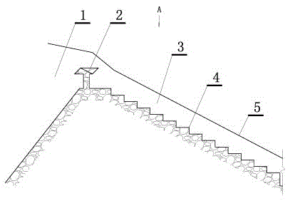
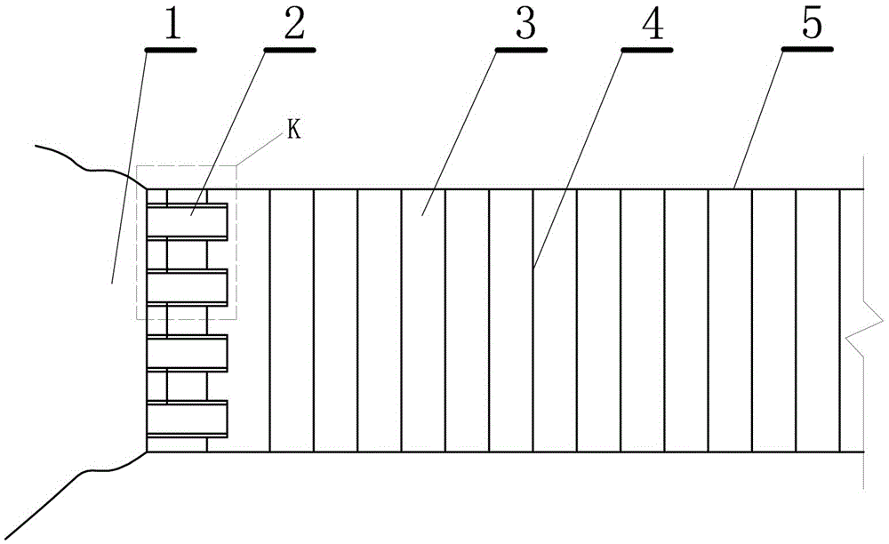
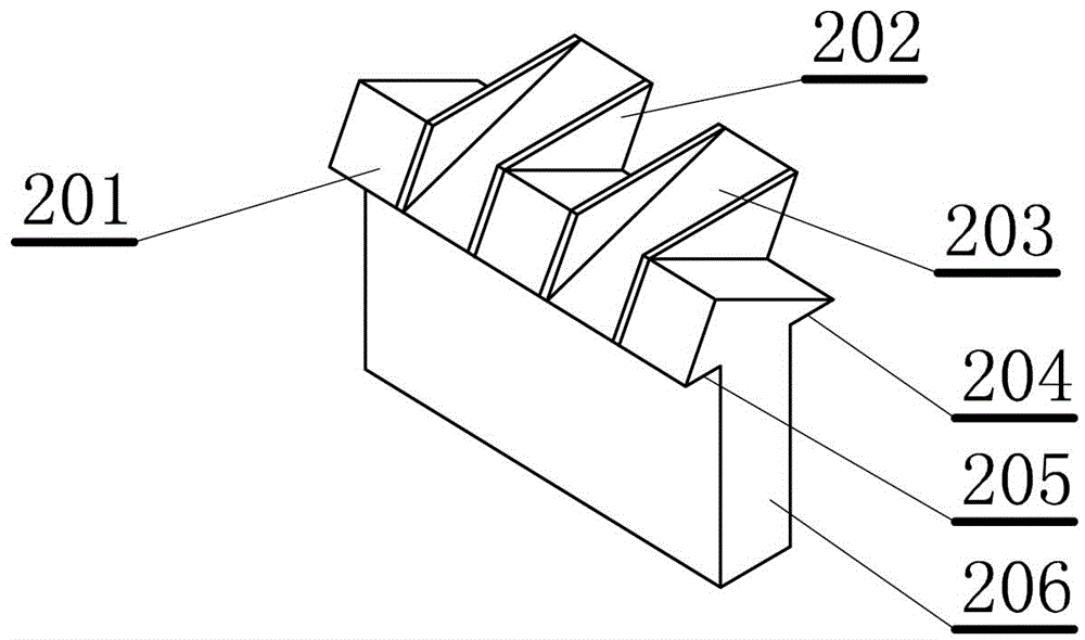
[0032] This embodiment is a combined super-discharge energy-dissipating flood unit, such as figure 1 , 2 , 3 shown. Including: an inlet overflow weir 2 arranged at the entrance 1 of the spillway, and the downstream of the inlet overflow weir is a steep groove 3 ( figure 2 The excavation side wall line 5 is used to indicate the depth of the steep groove), the steep groove is provided with a water drop energy dissipator 4, and the inlet overflow weir is a composite keyboard overflow weir, and the composite keyboard overflow The weir includes: a weir body 206, the top of the weir body is staggered with forward triangular piers 201 and reverse triangular piers 203 with a horizontal bottom surface, and the length of the bottom surfaces of the forward triangular piers and reverse triangular piers along the water flow direction exceeds The thickness of the top of the weir body forms the front cantilever 205 of the weir and the rear cantilever 204 of the weir; a dividing plate 202 ...

Embodiment 2

[0045] This embodiment is an improvement of the first embodiment, and it is a refinement of the first embodiment about the forward and reverse triangular piers and the partition. The water-facing surface of the forward triangular pier described in this embodiment is parallel to the backwater surface of the reverse triangular pier, and the shape of the partition plate is a parallelogram conforming to the section of the forward triangular pier and the reverse triangular pier along the water flow direction. like Figure 5 shown.

[0046] The shape of the parallelogram partition is determined by the shape of two triangular piers, or conversely, the two bases and two hypotenuses of the partition determine the ground, the water-facing surface and the back-water surface of the two triangular piers Angle.

Embodiment 3

[0048] This embodiment is an improvement of the above embodiment, and is a refinement of the above embodiment on the forward and reverse triangular piers. The bottom angle facing the water of the forward triangular pier described in this embodiment is greater than that of the reverse triangular pier.

[0049] The specific effect produced by this situation is: the water-facing surface of the forward triangular pier is relatively steep, while the water-facing surface of the reverse triangular pier is relatively gentle.


PUM


Abstract

The invention relates to an integrated super-discharge energy-dissipation flood-overflowing unit. The unit comprises an inlet overflow weir, wherein a chute is formed in the downstream of the inlet overflow weir; a water-falling energy dissipater is formed in the chute; the inlet overflow weir is a compound key overflow weir; the compound key overflow weir comprises a weir body; a forward triangular pier and a reverse triangular pier with horizontal bottom surfaces are staggered at the top of the weir body; the length in the water flow direction of the bottom surfaces of the positive triangular pier and the reverse triangular pier exceeds the thickness of the top end of the weir to form a weir front cantilever and a weir rear cantilever; a partition is arranged between the positive triangular pier and the reverse triangular pier. Compared with the conventional overflow weir, the compound key overflow weir has the advantages that the flow coefficient is remarkably increased; water heads acting on the weir are obviously reduced, so that a condition of heightening the dam for dealing with the exceeding flood caused by dam break and extreme climate. The integrated super-discharge energy-dissipation flood-overflowing unit is simple in structure and low in upgrading, improving and maintaining costs; by virtue of the open type arrangement, the sand is easily discharged; the unit is especially suitable for upgrading and improvement of the built wide-top weirs or practical weir flood spillway.

Description

technical field [0001] The invention relates to a combined super-discharging energy-dissipating spillover unit and a method, and is a hydraulic facility and a method, and is a hydraulic facility and a method for a spillway of a reservoir. Background technique [0002] Spillway is the most common water discharge control structure, which is generally used to vent the flood that cannot be accommodated by the planned storage and prevent flood from overflowing. For earth-rockfill dams, rockfill dams and some concrete dams, they need to be located on the bank or outside the dam body. The shore spillway is set at the natural pass. With the increasing frequency of extreme weather, the flood design standards of reservoir dams are constantly improving, because many existing rivers or river systems in the basin have become very complex, such as reservoirs formed by cascade development. Disaster factors such as dam breaks, extreme weather and other excessive floods. This puts forward ...

Claims


Application Information

Patent Timeline
Patent Type & Authority Patents(China)
IPC IPC(8): E02B8/06
CPCE02B8/06
Inventor 郭新蕾纪平夏庆福杨开林付辉王涛郭永鑫赵懿珺袁珏陈小莉梁洪华张强
Owner CHINA INST OF WATER RESOURCES & HYDROPOWER RES
Why Eureka
Try Eureka