Hydraulic buffering system and engineering machine

A hydraulic buffer and construction machinery technology, applied in the hydraulic field, can solve the problems of slow moving speed of the reversing valve core, difficult processing, easy blockage, etc.

Active Publication Date: 2015-07-01
SANY HEAVY MACHINERY
View PDF6 Cites 16 Cited by
  • Summary
  • Abstract
  • Description
  • Claims
  • Application Information

AI Technical Summary

Problems solved by technology

However, the actual effect achieved by this way of improving the oil circuit has certain defects
[0004] On the one hand, according to the working principle of the orifice and the throttle valve, generally speaking, the smaller the size of the orifice, the more obvious its hydraulic buffering effect, but this will cause the reversing spool to move too slowly, directly It affects the response speed of the arm cylinder or the boom cylinder, and affects the working efficiency of the excavator. Therefore, the setting of the size of the throttle hole is limited, and it can only play a certain role in mitigating, but cannot achieve the desired effect.
[0005] On the other hand, although the flow rate of the pilot oil circuit is controlled by increasing the orifice or the one-way throttle valve, thereby prolonging the closing time of the spool of the reversing valve to ease the hydraulic shock, however, at the moment when the reversing valve is closed, There will still be some hydraulic shock, especially if the boom lift of the excavator stops suddenly
[0006] On the other hand, due to the small size of the orifice or the throttle valve on the pilot oil circuit, it is not easy to process, the cost is high, and in the actual use process, it is very easy to be blocked, requiring maintenance and replacement, etc., which affects work efficiency

Method used


Image

  • Hydraulic buffering system and engineering machine

Examples


Embodiment Construction

[0027] It should be noted that, in the case of no conflict, the embodiments of the present invention and the features in the embodiments can be combined with each other. The present invention will be described in detail below with reference to the accompanying drawings and examples.

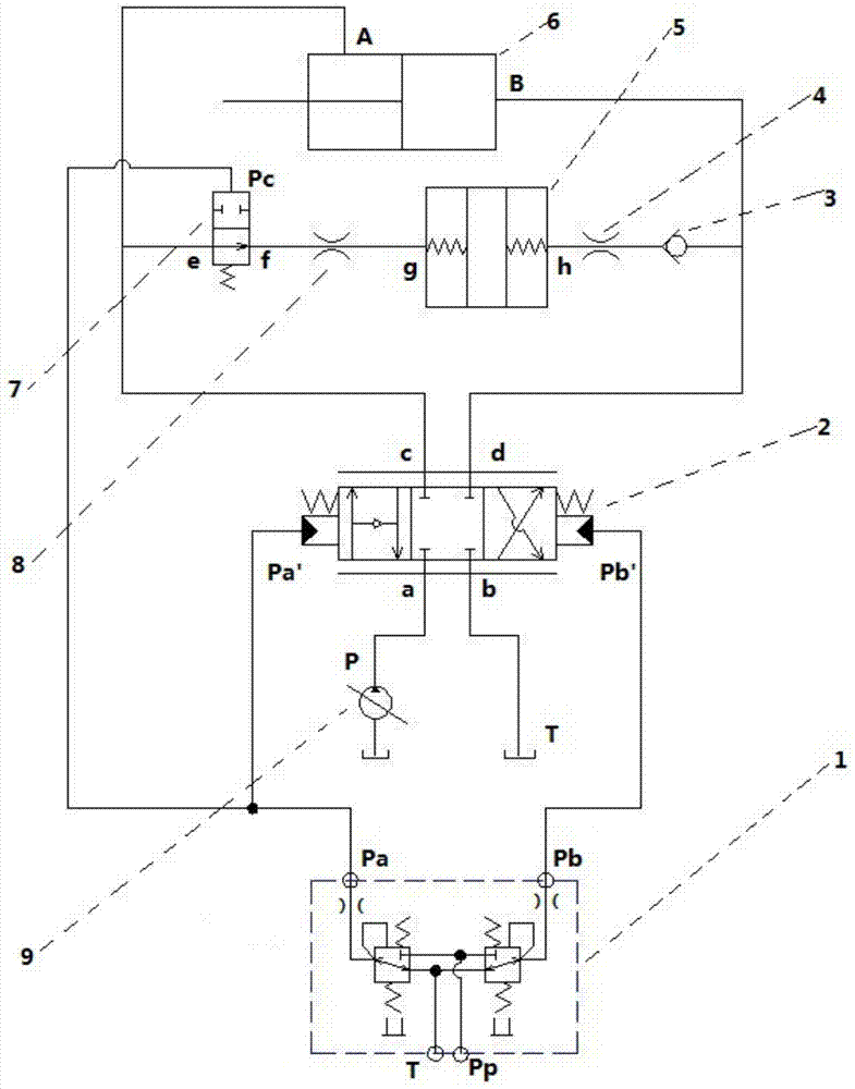
[0028] figure 1 It is a schematic structural diagram of a hydraulic buffer system provided by an embodiment of the present invention. Such as figure 1 As shown, the hydraulic buffer system includes an oil pump 9, a first reversing valve 2 and a hydraulic cylinder 6, and the oil pump 9 is respectively connected to the rod chamber and the rodless chamber of the hydraulic cylinder 6 through the first reversing valve 2, and the oil pump 9 passes through The first reversing valve 2 is also connected with a buffer oil circuit, and the hydraulic cylinder 6 is arranged in parallel with the buffer oil circuit, and the switch valve 7 and a buffer valve group are sequentially arranged in series on the buf...


PUM


Abstract

The invention relates to the technical field of hydraulics, and discloses a hydraulic buffering system and an engineering machine. The hydraulic buffering system comprises an oil pump, a first reversing valve, a hydraulic ram and a buffering oil passage. The oil pump is connected with a rod cavity and a rodless cavity of the hydraulic ram through the first reversing valve, the oil pump is connected with the buffering oil passage through the first reversing valve, the buffering oil passage and the hydraulic ram are arranged in parallel, and a switching valve and a buffering valve group are sequentially arranged on the buffering oil passage in series. According to the hydraulic buffering system and the engineering machine, the buffering oil passage is directly arranged in parallel relative to the rod cavity and the rodless cavity of the hydraulic ram, and the buffering valve group plays the buffering role selectively, so that under the condition that the regular work of the hydraulic ram and a main passage is not influenced, the hydraulic shock suffered by the hydraulic ram and related oil passages can be greatly relieved or even eliminated after a piston rod of the hydraulic ram suddenly stops stretching out and drawing back, components and parts of the hydraulic ram and the oil passages are protected from damage, and the service life is prolonged.

Description

technical field [0001] The invention relates to the technical field of hydraulic pressure, in particular to a hydraulic buffer system and construction machinery provided with the hydraulic buffer system. Background technique [0002] During the working process of the excavator, due to the actual needs of the working conditions or the personal operating habits of the driver, the working device (working cylinder) or motor of the excavator may suddenly start or brake suddenly. In the case of sudden start or braking, the hydraulic pipeline is suddenly closed, causing the moving hydraulic oil to produce a hydraulic shock, which eventually causes the excavator to vibrate or jump. Due to the structural characteristics of the motor itself, after integrating the balance valve and the delay valve, the hydraulic shock generated by its startup and braking has been controlled to a certain extent. However, the stick cylinder and the boom cylinder in the working cylinder, especially the l...

Claims


Application Information

Patent Timeline
Patent Type & Authority Applications(China)
IPC IPC(8): F15B15/22
CPCF15B15/22
Inventor 张炜叶其团闫海瑞
Owner SANY HEAVY MACHINERY
Why Eureka
Try Eureka