

Antenna, and antenna switching method and device
An antenna switching and antenna technology, which is applied to antenna grounding devices, devices that make antennas work in different frequency bands at the same time, antennas, etc.
- Summary
- Abstract
- Description
- Claims
- Application Information
AI Technical Summary
Problems solved by technology
Method used
Image

Examples
Embodiment 1
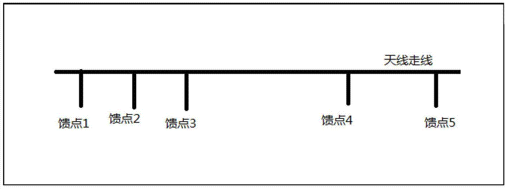
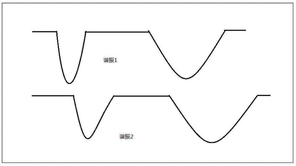
[0027] An embodiment of the present invention provides an antenna, which can switch access to the main feed point and the ground feed point of the antenna circuit so that the antenna circuit can obtain multiple different resonances, so that the antenna can cover a wider frequency band.
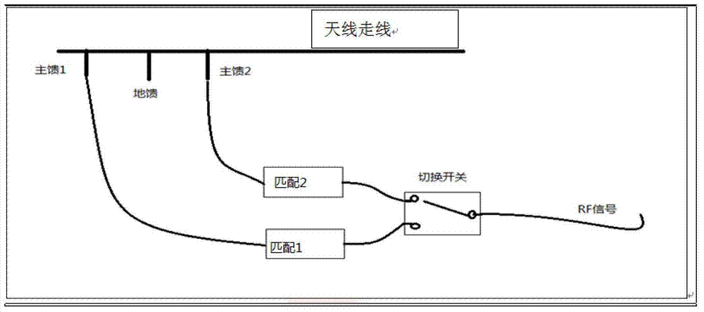
[0028] The antenna provided in this embodiment includes the following components: at least two main feed points, at least one ground feed point, matching circuits, and switchover switches; wherein, the number of feed points, the number of matching circuits, and the number of switchover switches can be It is determined according to the frequency band that the antenna needs to cover. For example, if more resonance is required, it can be achieved by increasing the number of main feed points, ground feed points, and switching switches. The switching switches can be single-pole double-throw switches or multiple A switch with the function of switching the access object, such as a knife multi-throw. ...
Embodiment 2
[0035] Based on the antenna provided in the above-mentioned embodiment 1, the feed point or the antenna wiring of the access antenna circuit can be switched in various ways, so that the antenna can generate multiple different resonances. This embodiment provides a variety of switching access antenna circuits way of feeding points.
[0036] The antenna switching method of this embodiment is mainly to control the main feed point and the ground feed point or the number of the main feed point and the ground feed point or the antenna routing connected to the antenna circuit according to the received control signal, Make the main feed point and the ground feed point connected to the antenna circuit in the working state to make the antenna circuit generate resonance corresponding to the control signal.
[0037] Wherein, controlling the main feed point and the ground feed point connected to the antenna circuit according to the received control signal specifically includes: according t...
Embodiment 3
[0048] This embodiment provides an antenna switching device. The device can be used to implement the above-mentioned antenna switching method. The device can be set in the antenna proposed by the present invention. The device includes a switching module, which is used to control the antenna according to the received control signal Connect the main feed point and the ground feed point of the antenna circuit, so that the main feed point and the ground feed point of the antenna circuit are in the working state. Specifically, the switching module is connected with the switch in the antenna, and by controlling the switch Select the feed point or antenna line that is connected to the antenna circuit.
[0049] Further, the above switching module can be specifically used for:
[0050] According to the frequency band indicated in the received control signal, select the feed point for accessing the antenna circuit from multiple main feed points and ground feed points set on the antenna ...
PUM
 Abstract
Description
Claims
Application Information