Liquid crystal metamaterial-based two-dimensional luneberg lens antenna

A technology of Lunbo lens antenna and Lunbo lens, which is applied in the direction of antenna, electrical components, radiation element structure, etc., can solve the problems of large loss, narrow bandwidth, and low efficiency of lens antennas, and achieve high operating frequency, low loss, Effect of high-precision gradient index

Inactive Publication Date: 2017-12-01
UNIV OF ELECTRONICS SCI & TECH OF CHINA
View PDF8 Cites 9 Cited by
  • Summary
  • Abstract
  • Description
  • Claims
  • Application Information

AI Technical Summary

Problems solved by technology

[0004] The technical problem to be solved by the present invention is the technical problem of large lens antenna loss, low efficiency and narrow bandwidth existing in the prior art

Method used


Image

  • Liquid crystal metamaterial-based two-dimensional luneberg lens antenna
  • Liquid crystal metamaterial-based two-dimensional luneberg lens antenna
  • Liquid crystal metamaterial-based two-dimensional luneberg lens antenna

Examples


Embodiment 1

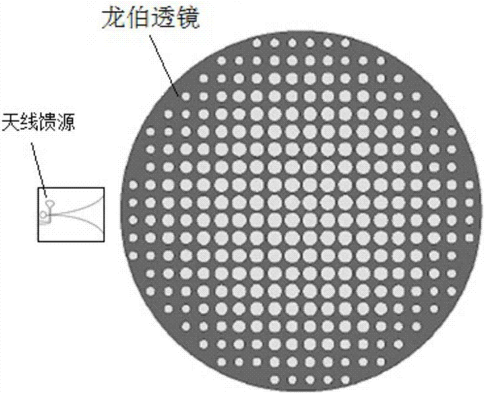
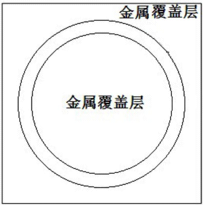
[0029] This embodiment provides a two-dimensional Luneberg lens antenna based on liquid crystal metamaterials, such as figure 1 , the two-dimensional Luneburg lens antenna includes a Luneburg lens, and an antenna feed placed on the surface of the Luneburg lens along the axial direction; as Figure 5 , the Lunberg lens includes at least one annular region, and the annular region is composed of a plurality of liquid crystal metamaterial units, such as Figure 4 , the liquid crystal metamaterial unit includes a first dielectric layer, a liquid crystal alignment layer, a liquid crystal cavity, a liquid crystal alignment layer, and a second dielectric layer that are horizontally overlapped and arranged in sequence; image 3 , the surface of the first medium layer is provided with a Lunberg lens structure patch; the liquid crystal cavity is used for filling liquid crystal metamaterials.

[0030] The liquid crystal chamber in this embodiment is composed of two liquid crystal alignme...

Embodiment 2

[0038] In this embodiment, on the basis of Embodiment 1, the antenna feed source in Embodiment 1 is a microstrip patch antenna.

[0039] Aperture antennas include dielectric rod-loaded horns and corrugated horns. Although they have a wide frequency band or cross-band, they have better pattern symmetry and consistency, lower cross-polarization components, high port isolation, and large power capacity. Advantages, it can ensure the uniform irradiation of the lens antenna, but there are problems of large volume and weight, relatively difficult processing, and inconvenient integration and compact design.

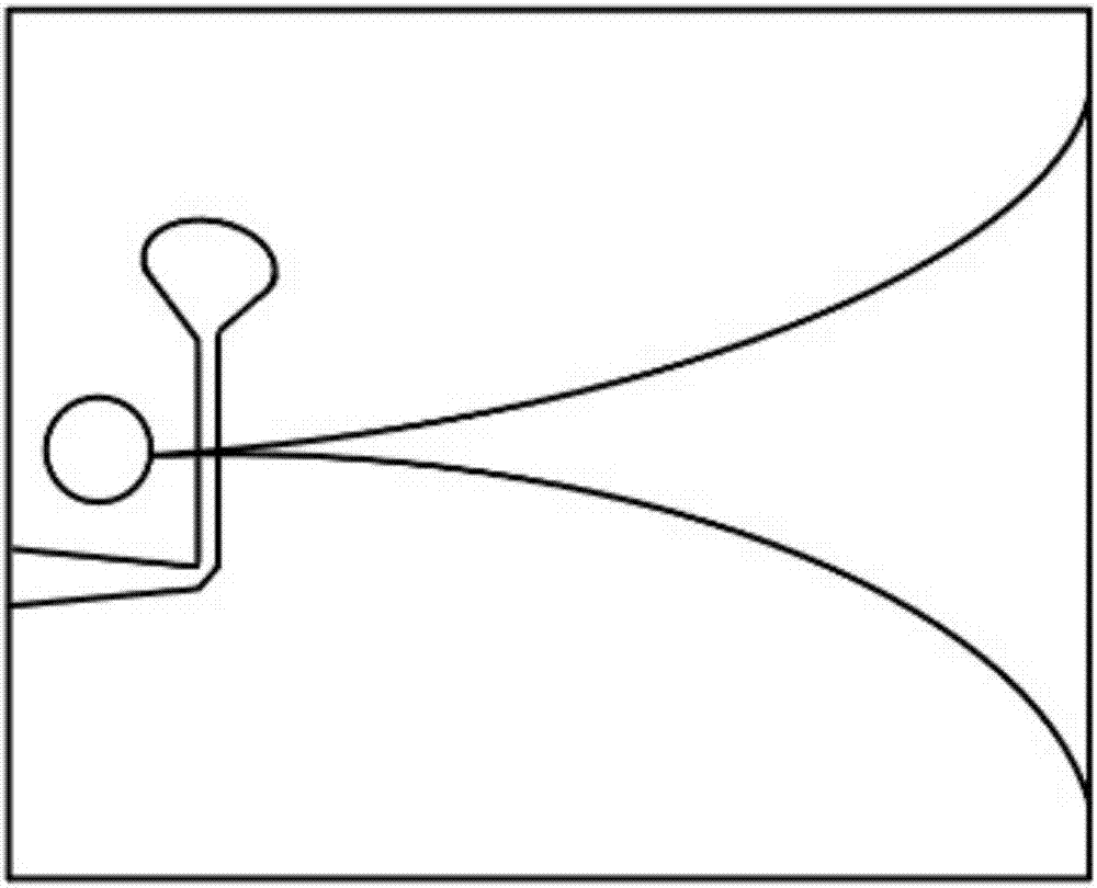
[0040] The microstrip patch antenna has flexible linear / circular polarization, simple manufacturing process and light weight for easy integration. Therefore, this embodiment adopts an exponentially changing slotted microstrip patch antenna with small size, easy integration, and wide bandwidth as the antenna feed source of the Lunberg lens antenna in this embodiment. Its structur...


PUM


Abstract

The invention relates to a liquid crystal metamaterial-based two-dimensional luneberg lens antenna, and aims at solving the technical problems that the lens antenna is great in loss, low in efficiency and small in bandwidth. According to the technical scheme, the two-dimensional luneberg lens antenna comprises a luneberg lens and an antenna feed source arranged on the surface of the luneberg lens along the axial direction, wherein the luneberg lens comprises at least one circle area; each circle area comprises a plurality of liquid crystal metamaterial units; each liquid crystal metamaterial unit comprises a first dielectric layer, one liquid crystal alignment layer, a liquid crystal cavity, another liquid crystal alignment layer and a second dielectric layer which horizontally overlap and are sequentially arranged; a luneberg lens structure patch is arranged on the surface of each first dielectric layer; and each liquid crystal cavity is used for being filled with a liquid crystal metamaterial, so that the problems are relatively well solved, and the liquid crystal metamaterial-based two-dimensional luneberg lens antenna can be applied to a microwave antenna.

Description

technical field [0001] The invention relates to the technical field of antennas, in particular to a two-dimensional Luneberg lens antenna based on liquid crystal metamaterials. Background technique [0002] The more widely used parabolic reflectors in multi-beam antennas have narrow beam coverage and large beam differences. In the process of multi-target tracking, relatively heavy antenna bases need to be rotated; although phased array antennas have a faster scanning speed, However, its beam coverage is limited, the loss is large, and the phase shift network is complex and expensive, which cannot meet the requirements of low-cost and efficient millimeter-wave communication systems. The lens in the field of optical imaging and focusing transforms different forms of divergent energy into plane waves, which greatly enriches the design of multi-beam antennas. The low-cost, wide-band, and wide-angle multi-beam scanning of lens antennas and feed network Features such as simplicit...

Claims


Application Information

Patent Timeline
Patent Type & Authority Applications(China)
IPC IPC(8): H01Q1/38H01Q15/00H01Q15/02H01Q19/06
CPCH01Q1/38H01Q15/0086H01Q15/02H01Q19/06
Inventor 蒋迪万应禄丁萍刘珂玮
Owner UNIV OF ELECTRONICS SCI & TECH OF CHINA
Why Eureka
Try Eureka