
Roller type weeding and soil loosening operation unit provided with retractable teeth
A technology of telescopic teeth and rollers, which is applied in the field of agricultural machinery, can solve the problems of reducing the effect of weeding and loosening soil, reducing the efficiency of machine tools, and increasing the amount of cleaning work, and achieves the effect of novel structure, good operation quality and high operation efficiency
- Summary
- Abstract
- Description
- Claims
- Application Information
AI Technical Summary
Problems solved by technology
Method used
Image

Examples
Embodiment Construction
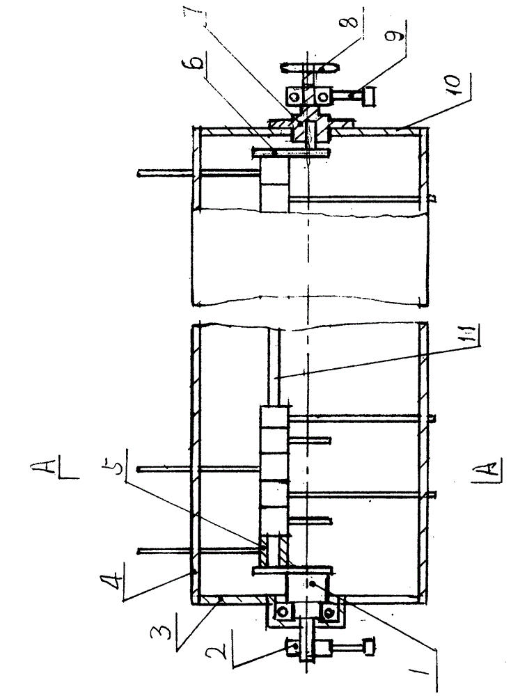
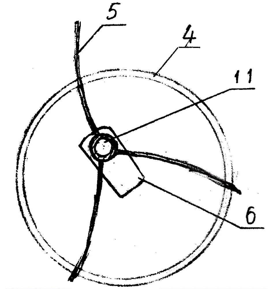
[0010] Embodiments of the present invention will be described in detail below in conjunction with the accompanying drawings. A retractable teeth drum type weeding and loosening operation unit, the left end cover 3 and the right end cover 10 are respectively fixed on the left and right ends of the drum 4, and the center part of the left end cover 3 is rotatably equipped with a support The crank shaft 1, the left part of the supporting crank shaft 1 is fixed on the positioning support seat 2, the drive shaft 7 is fixed on the center part of the right end cover 10, and the drive shaft 7 of the drive sprocket 8 is fixed It is rotatably inserted on the bearing seat assembly 9, and the crankshaft 6 is mated and installed relatively rotatably in the central hole of the drive shaft 7, and on the inner side wall surface of the supporting crankshaft 1 and the crankshaft 6, The telescopic pinion 11 is fixed at the inner part of the cylinder cavity of the drum 4. The central axis of the t...
PUM
 Abstract
Description
Claims
Application Information