A Design Method of UAV Directional Antenna Self-tracking System

A directional antenna and system design technology, applied in the direction of control using feedback, can solve the problems of tracking system motion fluctuations, increasing the complexity of the control system, and large fluctuations in tracking angle changes, so as to improve system reliability and adaptability, Improve maneuverability and concealment, reduce the effect of overhead tracking error

Active Publication Date: 2017-11-21
BEIHANG UNIV
View PDF6 Cites 0 Cited by
  • Summary
  • Abstract
  • Description
  • Claims
  • Application Information

AI Technical Summary

Problems solved by technology

However, based on the GPS position signal to design the directional antenna automatic tracking system, there are currently the following shortcomings: to determine the tracking target angle according to the relative position of the UAV and the directional antenna, the current calculation method needs to be based on the relative position of the directional antenna and the UAV. Judging the quadrant where the real azimuth is located, it is easy to cause ambiguity at the quadrant boundary, which increases the complexity of the control system and brings difficulties to engineering applications
Due to the limitations of the communication link transmission capability and the dynamic characteristics of the low-cost GPS receiver, the location update frequency sent by the UAV to the ground control system is usually low. Motion fluctuations and large tracking errors can significantly increase system wear
With the widespread application of unmanned aerial vehicles, the directional antenna tracking system is required to have maneuvering tracking capabilities in many application fields to improve the maneuverability and concealment of the system. However, during the maneuvering process, the GPS position information of the directional antenna is easily affected by tunnels, Interference from trees, buildings, etc. will cause inaccurate location information, resulting in the loss of tracking targets

Method used


Image

  • A Design Method of UAV Directional Antenna Self-tracking System
  • A Design Method of UAV Directional Antenna Self-tracking System
  • A Design Method of UAV Directional Antenna Self-tracking System

Examples


Embodiment Construction

[0030] The present invention is to provide a design method of a UAV directional antenna self-tracking system. The present invention will be described in detail below in conjunction with the accompanying drawings.

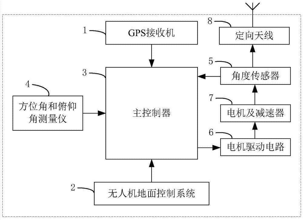
[0031] Such as figure 1 As shown, the directional antenna automatic tracking system applied in the present invention mainly includes: GPS receiver 1, unmanned aerial vehicle ground control system 2, master controller 3, azimuth and pitch angle measuring instrument 4, angle sensor 5, Motor drive circuit 6, motor and reducer 7 and directional antenna 8.

[0032]Install the GPS receiver 1 on the vehicle to obtain the position and speed of the directional antenna in real time, and send it to the main controller 3 . Utilize the UAV ground control system 2 to receive the position and speed of the UAV transmitted by the UAV in real time through the data link, and then forward it to the main controller 3 . The function that main controller 3 realizes is: Utilize the posit...


PUM


Abstract

The invention relates to a design method of a self-tracking system for a directional antenna of an unmanned aerial vehicle, which is used for the control of an unmanned aerial vehicle. In this method, a GPS receiver is installed on the vehicle to obtain the position and speed of the directional antenna in real time. The main controller uses the positions of the directional antenna and the UAV to obtain the tracking target angle of the directional antenna, and realizes it by using the speed of the directional antenna and the UAV. Predictive smoothing of position and implementation of adding feed-forward to azimuth motion as the drone flies over the directional antenna apex. The azimuth and elevation angle measuring instrument is installed on the vehicle to measure the current azimuth and elevation angle of the vehicle, and the current angle of the directional antenna is obtained by combining the measured value of the angle sensor. The main controller calculates the control amount according to the difference between the tracking target angle of the directional antenna and the current angle, and drives the directional antenna to reach the target position. The invention improves the maneuverability and concealment of the system, is easy to realize in engineering, effectively smooths the directional antenna tracking action, reduces overhead tracking errors, and improves system reliability and adaptability.

Description

technical field [0001] The invention belongs to the field of unmanned aerial vehicle control, relates to automatic tracking, in particular to a design method of an unmanned aerial vehicle directional antenna self-tracking system. Background technique [0002] With the rapid development of UAV technology, the application is more and more extensive. In many applications, there is a large amount of observation and control data between the UAV and the ground control system that needs to be transmitted in real time. In order to ensure the accuracy and reliability of data transmission and reception, and at the same time improve the receiving gain and anti-interference ability, this long-distance, high-bandwidth communication, Usually a directional antenna is used. When the directional antenna works, only when the main lobe of the transmitting antenna and the receiving antenna are aligned, there is a higher gain. If the real-time alignment of the directional antenna cannot be gua...

Claims


Application Information

Patent Timeline
Patent Type & Authority Patents(China)
IPC IPC(8): G05D3/12
Inventor 丁希仑查长流俞玉树王学强
Owner BEIHANG UNIV
Why Eureka
Try Eureka