Unmanned aerial vehicle directional antenna self-tracking system design method

A directional antenna and system design technology, applied in the direction of control using feedback, can solve problems such as increased system wear, loss of tracking targets, and large tracking errors

Active Publication Date: 2015-09-23
BEIHANG UNIV
View PDF6 Cites 30 Cited by
  • Summary
  • Abstract
  • Description
  • Claims
  • Application Information

AI Technical Summary

Problems solved by technology

However, based on the GPS position signal to design the directional antenna automatic tracking system, there are currently the following shortcomings: to determine the tracking target angle according to the relative position of the UAV and the directional antenna, the current calculation method needs to be based on the relative position of the directional antenna and the UAV. Judging the quadrant where the real azimuth is located, it is easy to cause ambiguity at the quadrant boundary, which increases the complexity of the control system and brings difficulties to engineering applications
Due to the limitations of the communication link transmission capability and the dynamic characteristics of

Method used


Image

  • Unmanned aerial vehicle directional antenna self-tracking system design method
  • Unmanned aerial vehicle directional antenna self-tracking system design method
  • Unmanned aerial vehicle directional antenna self-tracking system design method

Examples


Embodiment Construction

[0030] The present invention is to provide a design method of a UAV directional antenna self-tracking system. The present invention will be described in detail below in conjunction with the accompanying drawings.

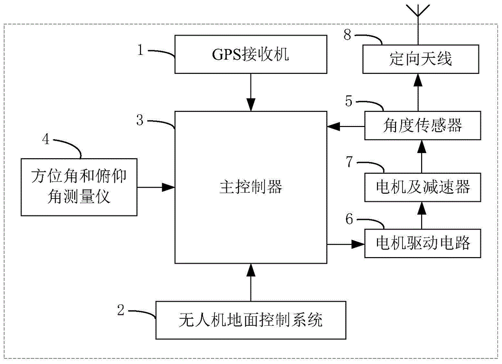
[0031] Such as figure 1 As shown, the directional antenna automatic tracking system applied in the present invention mainly includes: GPS receiver 1, unmanned aerial vehicle ground control system 2, master controller 3, azimuth and pitch angle measuring instrument 4, angle sensor 5, Motor drive circuit 6, motor and reducer 7 and directional antenna 8.

[0032]Install the GPS receiver 1 on the vehicle to obtain the position and speed of the directional antenna in real time, and send it to the main controller 3 . Utilize the UAV ground control system 2 to receive the position and speed of the UAV transmitted by the UAV in real time through the data link, and then forward it to the main controller 3 . The function that main controller 3 realizes is: Utilize the posit...


PUM


Abstract

The invention provides an unmanned aerial vehicle directional antenna self-tracking system design method which is used for unmanned aerial vehicle control. According to the method, a GPS receiver is installed on a carrier vehicle to acquire the position and speed of a directional antenna in real time. The tracking target angle of the directional antenna is acquired by a master controller via utilizing the position of the directional antenna and an unmanned aerial vehicle. Position prediction smoothing is realized by utilizing speed of the directional antenna and the unmanned aerial vehicle, and feedforward is increased for azimuth movement when the unmanned aerial vehicle flies over the vertex of the directional antenna. Azimuth angle and pitch angle measuring instruments are installed on the carrier vehicle to measure the current azimuth angle and the pitch angle of the carrier vehicle, and the current angle of the directional antenna is acquired via combination of the measured value of an angle sensor. The control variable is calculated by the master controller according to the difference value of the tracking target angle and the current angle of the directional antenna so that the directional antenna is driven to reach the target position. System mobility and concealment are enhanced, project realization is easy, tracking movement of the directional antenna is effectively smoothed, vertex passing tracking error is reduced and system reliability and adaptability are enhanced.

Description

technical field [0001] The invention belongs to the field of unmanned aerial vehicle control, relates to automatic tracking, in particular to a design method of an unmanned aerial vehicle directional antenna self-tracking system. Background technique [0002] With the rapid development of UAV technology, the application is more and more extensive. In many applications, there is a large amount of observation and control data between the UAV and the ground control system that needs to be transmitted in real time. In order to ensure the accuracy and reliability of data transmission and reception, and at the same time improve the receiving gain and anti-interference ability, this long-distance, high-bandwidth communication, Usually a directional antenna is used. When the directional antenna works, only when the main lobe of the transmitting antenna and the receiving antenna are aligned, there is a higher gain. If the real-time alignment of the directional antenna cannot be gua...

Claims


Application Information

Patent Timeline
IPC IPC(8): G05D3/12
Inventor 丁希仑查长流俞玉树王学强
Owner BEIHANG UNIV
Why Eureka
Try Eureka