Transmission cavity frequency stabilizing system and method for realizing long-term laser frequency stabilization

A technology of frequency stabilization and transmission cavity, which is applied to the transmission cavity frequency stabilization system and its frequency stabilization field with long-term laser frequency stability, which can solve the problem of not being able to take into account the continuous tuning of the laser frequency, long-term stability, narrow line width, space waste, etc. problems, to achieve long-term stable laser linewidth, simple principle and device, and strong scalability

Active Publication Date: 2015-09-30
EAST CHINA NORMAL UNIV
View PDF5 Cites 7 Cited by
  • Summary
  • Abstract
  • Description
  • Claims
  • Application Information

AI Technical Summary

Problems solved by technology

[0005] The purpose of the present invention is to disclose a transmission cavity frequency stabilization system with long-term stable laser frequency and its frequency stabilization method to solve the problem that the traditional Ti:sapphire laser frequency stabilization technology cannot take into account the continuous tuning, long-term stability and line width of the laser frequency at the same time. narrow, and a set of frequency stabilization system can only lock one beam of laser, resulting in waste of space and high cost. It provides multiple beams with narrow linewidth and long-term frequency stability for the fields of laser physics, atomic and molecular optics, frequency standards, and quantum information. laser

Method used


Image

  • Transmission cavity frequency stabilizing system and method for realizing long-term laser frequency stabilization
  • Transmission cavity frequency stabilizing system and method for realizing long-term laser frequency stabilization
  • Transmission cavity frequency stabilizing system and method for realizing long-term laser frequency stabilization

Examples


Embodiment Construction

[0033] The specific implementation manner of the present invention will be described in detail in conjunction with the technical scheme and the accompanying drawings.

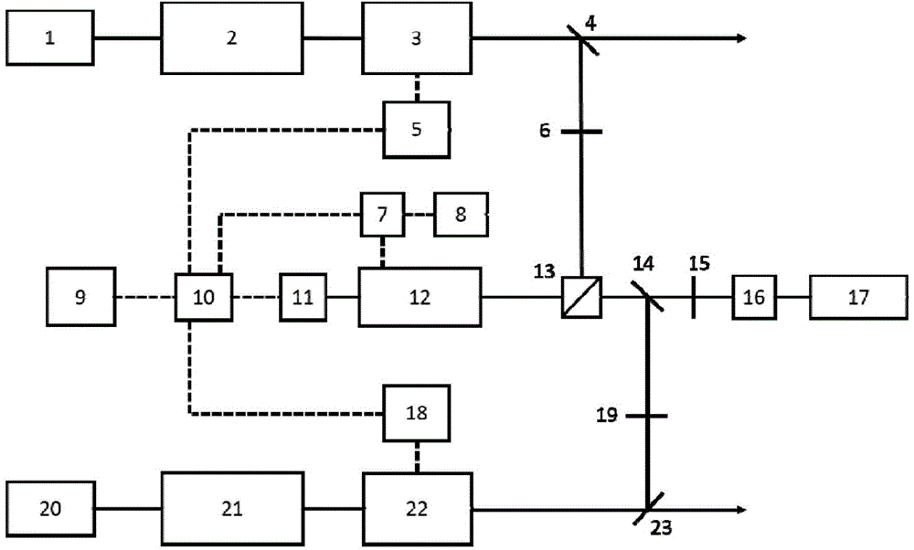
[0034] In this embodiment, the models of the Ti:Sapphire lasers are Matisse TS from Sirah Company in Germany, wherein the pump sources 1 and 20 are Millennia eV, and the reference cavities 3 and 22 are temperature-controlled reference cavities placed in a low vacuum. The Fabry-Perot transmission cavity 12 is the FPI100 confocal cavity of Toptica Company, the frequency-stabilized reference laser 17 is the HRS015 He-Ne laser of Thorlabs Company, and the model of the data acquisition card 10 is PCI-6259 of NI Company.

[0035] A transmission cavity frequency stabilization system with long-term stable laser frequency, which can simultaneously stabilize the frequency of two Ti:Sapphire lasers as an example, such as figure 1As shown, the Ti:Sapphire laser includes a pump source and a ring cavity. The output port of t...


PUM


Abstract

The invention discloses a transmission cavity frequency stabilizing system and method for realizing long-term laser frequency stabilization and belongs to the field of precise laser frequency stabilization. The frequency stabilizing system mainly comprises a plurality of Ti-doped sapphire lasers, reference cavities, control boxes, a reference laser (helium-noon laser) with stable frequency, a polarization beam splitter, a Fabry-Perot transmission cavity, a photoelectric detector, a function signal generator, an adder, a data acquisition card, a computer and the like. The frequency stabilizing method comprises steps as follows: firstly, two Ti-doped sapphire lasers are locked on the respective reference cavities, and then the reference cavities are locked on the reference laser with stable frequency, so that two Ti-doped sapphire lasers with laser line width smaller than 100 kHz and long-term frequency drift smaller than plus/minus 1 MHz are obtained. The system and the method have the advantages that only one reference laser is used for locking the plurality of Ti-doped sapphire lasers with frequency to be stabilized simultaneously and can lock the Ti-doped sapphire lasers at any frequency within the tunable range, and the extensibility and the frequency stability are very high.

Description

technical field [0001] The invention belongs to laser frequency stabilization technology, and relates to a transmission cavity frequency stabilization system with long-term stable laser frequency and a frequency stabilization method thereof, which is applicable to laser physics, atomic and molecular optics, frequency standards, quantum information and other fields requiring long-term stable frequency lasers . Background technique [0002] Lasers with long-term frequency stability are very important in scientific experiments in many fields. There are various ways to achieve laser frequency stabilization, including reference cavity frequency locking technology, saturated absorption frequency stabilization technology, etc. Different frequency stabilization methods have their own advantages and disadvantages. For example, reference The cavity frequency locking method can narrow the linewidth, but it is difficult to overcome the long-term frequency drift. The saturated absorption...

Claims


Application Information

Patent Timeline
Patent Type & Authority Applications(China)
IPC IPC(8): H01S3/13
Inventor 尹燕宁夏勇杨秀秀李兴佳徐素鹏印建平
Owner EAST CHINA NORMAL UNIV
Why Eureka
Try Eureka