
Passive laser gyroscope

A laser gyroscope and gyroscope technology, applied in the field of laser technology, can solve the problems of improving the stability of the cavity, reducing the stability of the gyroscope, limitations, etc., to achieve the stability of the laser frequency, the narrowing and narrowing of the laser line width, and the improvement of precision and sensitivity. Effect

Active Publication Date: 2013-04-17
NAT INST OF METROLOGY CHINA
View PDF3 Cites 11 Cited by
  • Summary
  • Abstract
  • Description
  • Claims
  • Application Information

AI Technical Summary

Problems solved by technology

However, in the traditional gyroscope, for the former, the general ring cavity, especially the ring cavity with a larger ring area, is difficult to effectively suppress external interference, thus reducing the stability of the gyroscope.
Therefore, the improvement of the stability of the cavity is limited by the technical
As for the latter, because the line width and stability of ordinary lasers are not very good, this also directly limits the accuracy of the laser gyroscope.

Method used


Image

  • Passive laser gyroscope
  • Passive laser gyroscope
  • Passive laser gyroscope

Examples


Embodiment Construction

[0024] The present invention will be described more fully hereinafter with reference to the accompanying drawings, in which exemplary embodiments of the invention are illustrated.

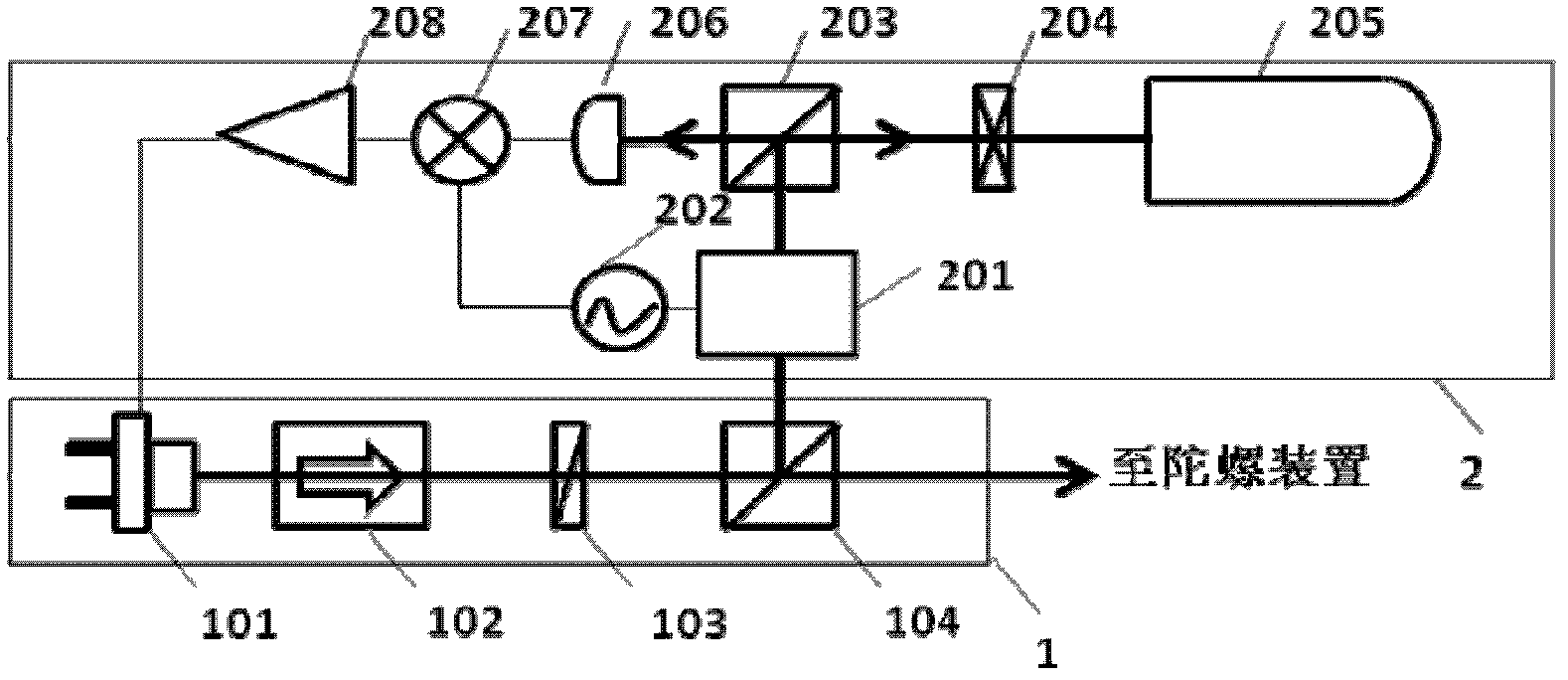
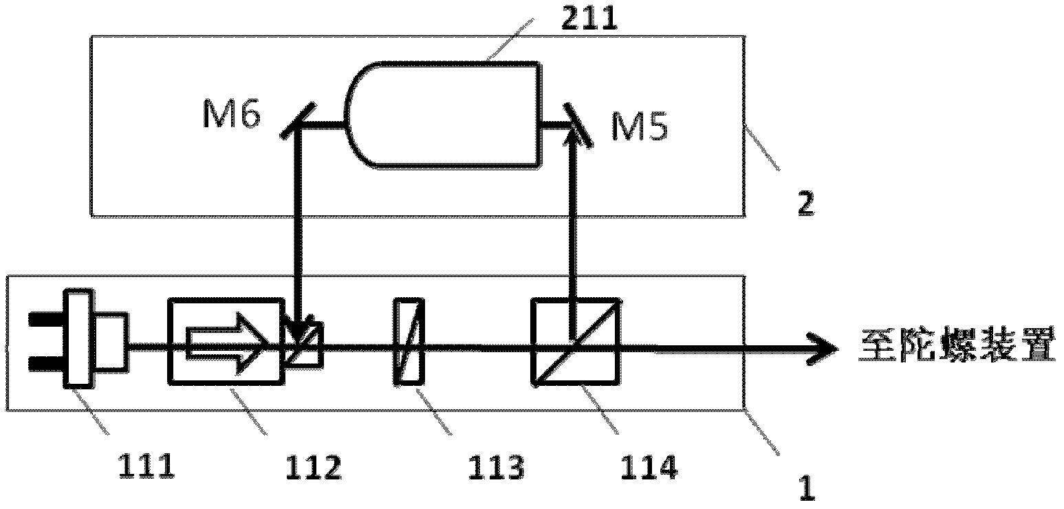
[0025] figure 1 It is a schematic diagram of an embodiment of the passive laser gyroscope of the present invention. Such as figure 1 As shown, the laser gyro includes a laser device 1, a line width narrowing feedback device 2, and a gyro device 3. The line width narrowing feedback device 2 also includes a Fabry-Perot FP cavity, and the gyro device 3 also includes a ring cavity ,in:

[0026] The laser device 1 is used to respectively output the first laser signal to the line width narrowing feedback device 2, output the second laser signal to the gyro device 3, and use the laser signal or electrical signal fed back by the line width narrowing feedback device 2 to control the laser device. 1. The center frequency of the output second laser signal is locked to the resonant frequency of the FP cavit...


PUM


Abstract

The invention discloses a passive laser gyroscope, comprising a laser apparatus, a line-width reduction feedback device and a gyroscope apparatus, wherein the laser apparatus outputs a first laser signal to the line-width reduction feedback device and outputs a second laser signal to the gyroscope apparatus; the line-width reduction feedback device provides the first laser signal to an FP cavity and feeds the laser signal outputted by the FP cavity or an electric signal converted from the laser signal back to the laser apparatus; the laser apparatus locks a central frequency of the first laser signal outputted by the laser apparatus as a resonant frequency of the FP cavity by using the feedback signal; the gyroscope apparatus receives the second laser signal outputted by the laser apparatus; and rotation angular velocity of the gyroscope apparatus is determined by using the line-width reduction laser signal. The central frequency of the laser signal is locked as the resonant frequency of the FP cavity by using a feedback signal mode, so that stability of line-width reduction and the laser frequency of the laser outputted by the laser apparatus can be realized; and precision and sensitivity for measurement of the rotation angular velocity of the laser gyroscope can be increased.

Description

technical field [0001] The invention relates to laser technology, in particular to a passive laser gyroscope. Background technique [0002] As the core inertial device of the inertial navigation system, the gyroscope can be used to measure the small changes in the direction of the aircraft during flight, which helps the inertial navigation system to continuously calculate the position, speed and direction of the aircraft, and realize the aircraft without external reference. Therefore, gyroscopes play a very important role in many fields of national defense science and technology and national economy. Since the invention of laser in the 1960s, research on optical inertial navigation based on the Sagnac effect has developed rapidly. Compared with the traditional mechanical gyroscope, since it does not need to move components during operation, its reliability and resolution have a lot of room for improvement. According to the geometric relationship between the laser gain medi...

Claims


Application Information

Patent Timeline
Patent Type & Authority Applications(China)
IPC IPC(8): G01C19/66
Inventor 臧二军王少凯李烨曹建平方占军
Owner NAT INST OF METROLOGY CHINA
Learn More