
An aerial work platform

A technology for aerial work platforms and fixed platforms, which is applied in the direction of lifting devices, etc., and can solve problems such as the offset between guide rods and guide rails

Active Publication Date: 2018-04-20
HUNAN SINOBOOM HEAVY IND
View PDF6 Cites 0 Cited by
  • Summary
  • Abstract
  • Description
  • Claims
  • Application Information

AI Technical Summary

Problems solved by technology

[0007] In view of this, the object of the present invention is to provide an aerial work platform that can effectively solve the problem of offset between the guide rod and the guide rail

Method used


Image

  • An aerial work platform
  • An aerial work platform
  • An aerial work platform

Examples


Embodiment Construction

[0022] The embodiment of the invention discloses an aerial work platform to effectively solve the problem of offset between a guide rod and a guide rail.

[0023] The following will clearly and completely describe the technical solutions in the embodiments of the present invention with reference to the accompanying drawings in the embodiments of the present invention. Obviously, the described embodiments are only some, not all, embodiments of the present invention. Based on the embodiments of the present invention, all other embodiments obtained by persons of ordinary skill in the art without making creative efforts belong to the protection scope of the present invention.

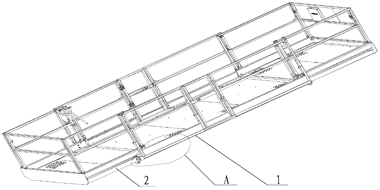
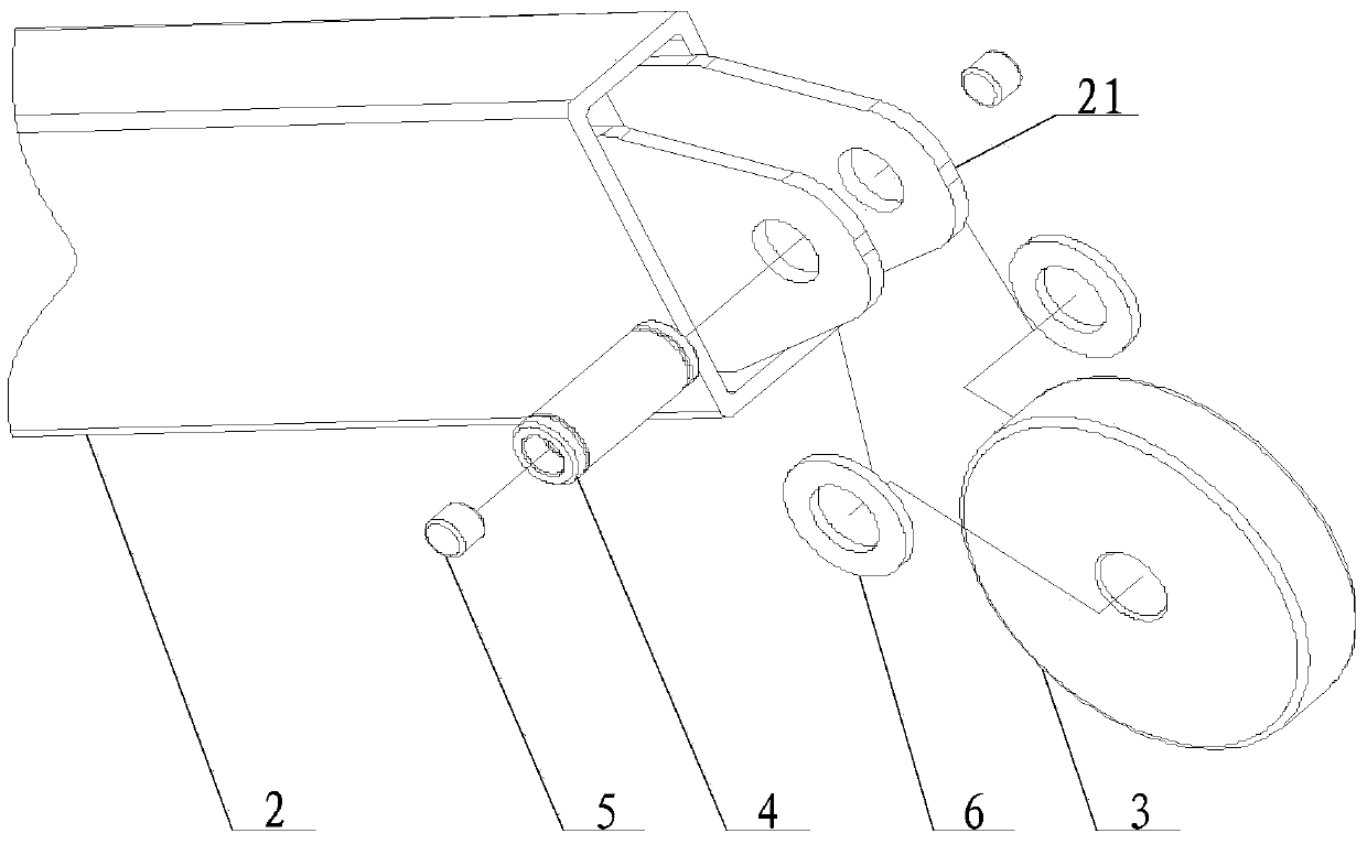
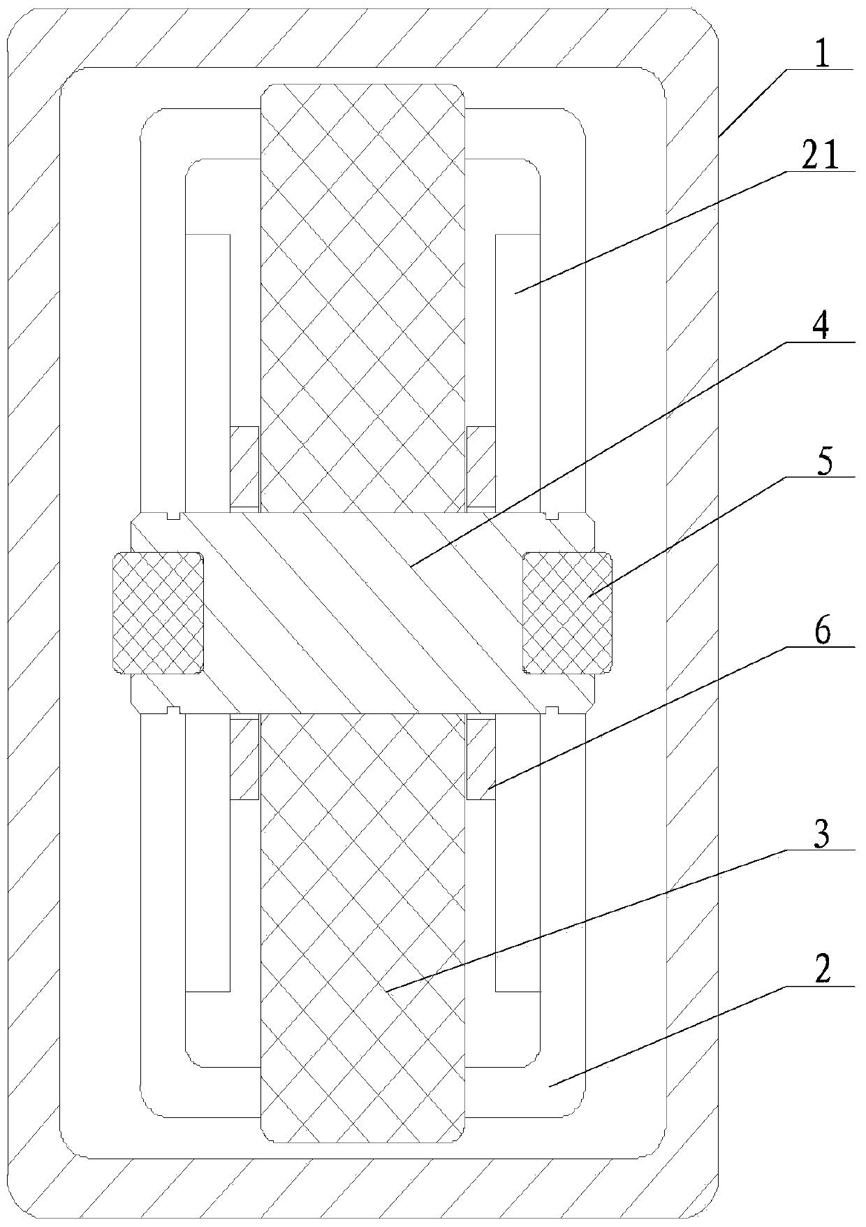
[0024] see Figure 1-Figure 3 , figure 1 A schematic diagram of the installation structure of the movable platform and the fixed platform provided by the embodiment of the present invention; figure 2 for figure 1 Partial structural schematic diagram of part A; image 3 for figure 1 Schematic diagram o...


PUM


Abstract

The invention discloses an aerial work platform. The work platform comprises a fixed platform and a movable platform, the fixed platform and the movable platform are in sliding fit with a guide rod through a guide rail, a pulley which can slide in the guide rail and a pin shaft which is used for hinging the pulley to the guide rod are arranged at one end of the guide rod, and the work platform further comprises abutting-against pieces which are installed at the two ends of the pin shaft and can prevent the side wall of the guide rail from being in contact with the side wall of the guide rod; when the pulley reaches the preset position, the abutting-against pieces can move in the axis direction of the pin shaft. When the pulley is within the offset-permitted range, the circumstance that friction force between the abutting-against pieces and the guide rail is generated, so that the frictional wear is caused can be avoided through the abutting-against pieces, and meanwhile the relative sliding between the guide rail and the guide rod is guaranteed. After the pulley breaks away from the preset position, the abutting-against pieces are located between the side wall of the guide rail and the pin shaft, and the side wall of the guide rail can be prevented from abutting against the guide rod so that the abutting-against problem between the guide rod and the guide rail can be effectively solved.

Description

technical field [0001] The invention relates to the technical field of high-altitude operation equipment, and more specifically, relates to a high-altitude operation platform. Background technique [0002] An aerial work platform is a common aerial work equipment, which mainly includes a base, a lifting device and a working platform. Among them, the base is generally equipped with a wheel walking device, the main function is to facilitate the movement of the aerial work platform. The lower end of the lifting device is fixedly connected to the base, and the upper end is fixedly connected to the working platform. The lifting device is generally driven by the driving device to lift, that is, to drive the working platform to move up and down. The lifting device is a scissor lifting device and a folding arm lifting device. Or other types of lifting devices. Among them, the work platform is the support platform for the aerial workers, that is, the lifting device drives the work ...

Claims


Application Information

Patent Timeline
Patent Type & Authority Patents(China)
IPC IPC(8): B66F11/04
CPCB66F11/04B66F2700/09
Inventor 刘国良吴宇佳
Owner HUNAN SINOBOOM HEAVY IND
Learn More