Robot tail end positioning deviation correction method and system

A correction method and a correction system technology, applied to instruments, measuring devices, optical devices, etc., can solve problems such as the influence of galvanometer correction and the large error in position deviation calculation

Active Publication Date: 2015-11-18
深圳市大族机器人有限公司
View PDF8 Cites 56 Cited by
  • Summary
  • Abstract
  • Description
  • Claims
  • Application Information

AI Technical Summary

Problems solved by technology

Compared with the traditional manual correction method, this method has higher accuracy, but there are still deficiencies.
The disadvantage is that this method directly uses the CCD image acquisition device to collect all the marking points in

Method used


Image

  • Robot tail end positioning deviation correction method and system
  • Robot tail end positioning deviation correction method and system
  • Robot tail end positioning deviation correction method and system

Examples


Embodiment Construction

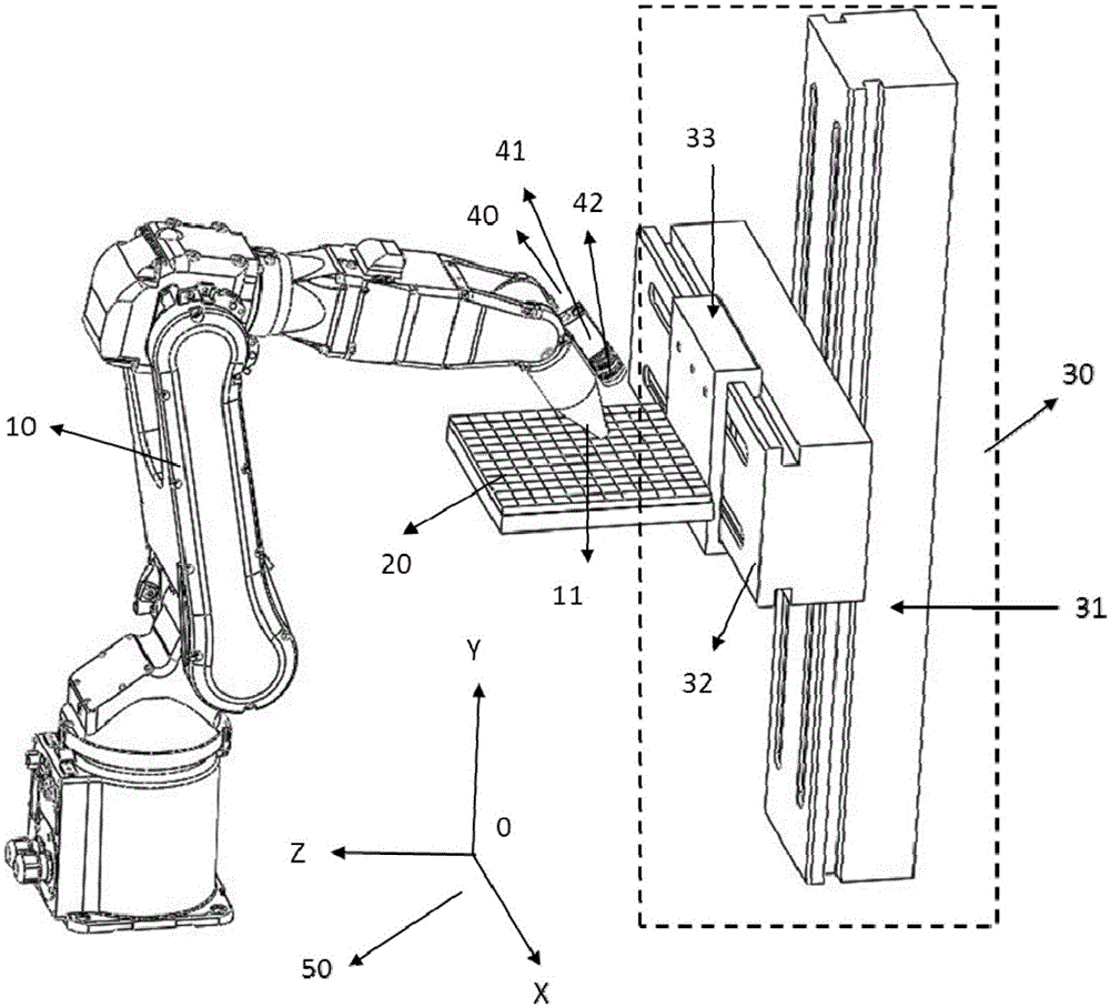
[0031] figure 1 Shown is a schematic structural diagram of a general robot end positioning deviation correction system of the present invention. The general robot end correction system refers to correcting the spatial positioning error of the manipulator end to obtain a spatial position error correction table. The invention mainly uses industrial cameras and visual algorithms to obtain the positioning deviation of the robot end, obtains the error distribution of the robot's positioning, and software compensation makes the robot's end positioning more accurate.

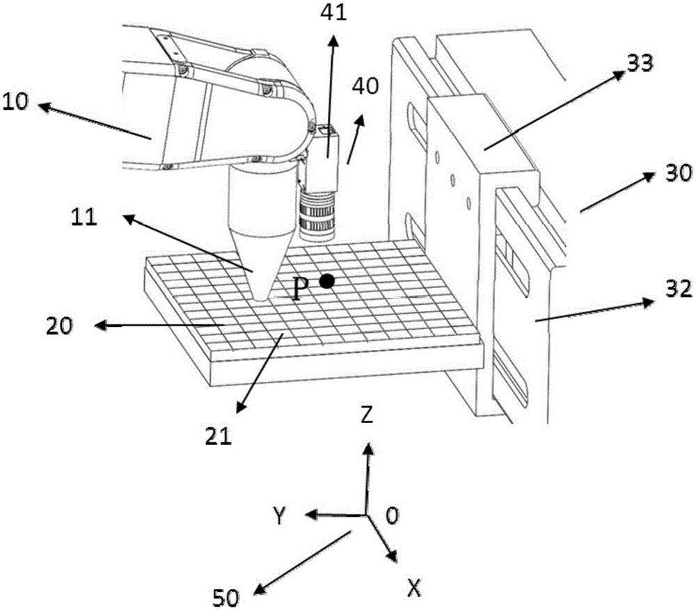
[0032] In order to realize the high-precision end positioning of the robot, the present invention proposes a universal robot end calibration system, which includes: a manipulator 10, an execution end 11 located at the end of the manipulator 10, an object calibration plate 20 for the execution end 11 to work, and a fixed and driven The high-precision motion platform 30 on which the calibration plate 20 moves, and the im...


PUM


Abstract

The invention provides a robot tail end positioning deviation correction method and system. The present includes the following steps that: 101, a camera calibration system is set; 102, the relative positions of the tail end of a manipulator and the center of a camera are calibrated; 103, the camera photographs the images of all mark points in a calibration plate and analyzes the images so as to obtain a series of deviation quantity data under the condition that the tail end of the manipulator drives the camera to move and traverse different Z values; and 104, a space deviation distribution table is constructed; and 105, the deviation of the tail end of the robot can be obtained based on the space deviation distribution table. According to the method and system of the invention, the calibration coefficient of the camera is calibrated; the relative positions of the tail end of the manipulator and the center of the camera are calibrated; the camera photographs the images of all the mark points in the calibration plate and analyzes the images so as to obtain deviation quantity under the condition that the tail end of the manipulator drives the camera to move and traverse different Z values, and the deviation correction table is stored; and manipulator positioning is compensated through searching the deviation correction table, and the manipulator can move to a set position.

Description

technical field [0001] The invention is applicable to the fields of robot end calibration, positioning and correction, and in particular relates to a method and system for correcting positioning deviation of a robot end. Background technique [0002] In the field of laser processing, a large number of galvanometers are used for scanning processing. Due to the installation of the galvanometer and various other reasons, the processed image in the scanning area will have various deformations. However, the traditional method of manual measurement is difficult to achieve 0.1 Positioning accuracy below millimeters. [0003] The publication date is August 26, 2009, and the Chinese invention patent application with the application number 200910105786.2 discloses a galvanometer correction system and correction method. The method uses a CCD image acquisition device to locate the matrix target, and uses a correction processing module to output Compensation file for galvo. Compared wi...

Claims


Application Information

Patent Timeline
IPC IPC(8): G01B11/00
Inventor 周蕾李玉廷王光能舒远李人杰高云峰
Owner 深圳市大族机器人有限公司
Why Eureka
Try Eureka