A reliability monitoring method for gas turbine hot end components

A technology for gas turbines and hot-end components, applied in gas turbine engine testing, jet engine testing, etc., can solve problems such as increased gas turbine accident rate, accelerated damage and destruction of gas turbine hot-end components, accelerated failure of high-temperature components, etc.

Active Publication Date: 2017-09-22
ELECTRIC POWER RES INST OF GUANGDONG POWER GRID +1
View PDF6 Cites 0 Cited by
  • Summary
  • Abstract
  • Description
  • Claims
  • Application Information

AI Technical Summary

Problems solved by technology

In terms of service performance prediction, with the development of fracture mechanics, damage mechanics and modern fatigue design theory, as well as the maturity of high-temperature hot-end component monitoring / failure analysis technology, people gradually realize that complex loads and high-temperature extreme environments caused by power plant start-up and shutdown The interaction will greatly accelerate the damage and destruction of the hot end parts of the gas turbine, which poses a severe test to its performance and life prediction
As the research report of the National Aeronautics and Space Administration (NASA) pointed out: the coupling effect of creep fatigue load and the environment leads to accelerated failure of high-temperature components, which in turn leads to an increase in the rate of gas turbine accidents year by year, and the structural integrity evaluation and reliability assurance of gas turbines are facing new challenges
At the level of life design, the life design method based solely on fatigue or creep cannot be used for life extrapolation under chemical-mechanical multi-field coupling conditions (fatigue-creep-oxidation). Existing model methods and life design criteria Whether it is applicable to the creep fatigue life assessment of key high-temperature components needs to be re-examined

Method used


Image

  • A reliability monitoring method for gas turbine hot end components
  • A reliability monitoring method for gas turbine hot end components
  • A reliability monitoring method for gas turbine hot end components

Examples


Embodiment Construction

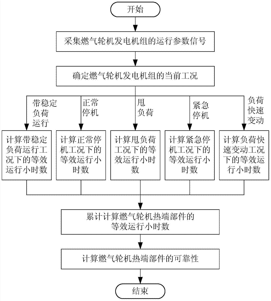
[0048] Such as figure 1 As shown, the steps of the method for reliability monitoring of the gas turbine hot end components in this embodiment include:

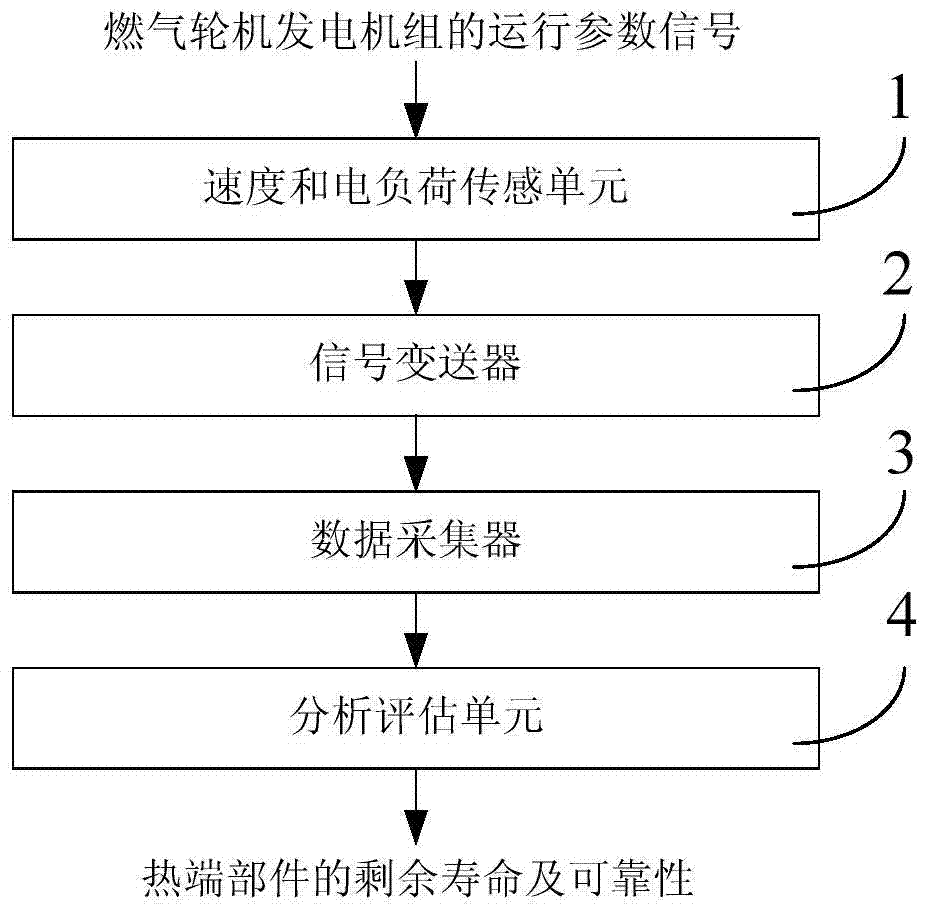
[0049] 1) Collect the operating parameter signal of the gas turbine generator set;

[0050] 2) Determine the current working condition of the gas turbine generating set according to the electrical load of the unit and the operating parameter signal of the rotor speed;

[0051] 3) Calculate the equivalent operating hours of the gas turbine generator set under the current working conditions;

[0052] 4) Calculate the equivalent operating hours of the hot end parts of the gas turbine according to the equivalent operating hours under each working condition;

[0053] 5) Calculate the remaining life and reliability of the hot end components of the gas turbine based on the equivalent operating hours of the hot end components of the gas turbine.

[0054] In this embodiment, by collecting the operating parameter signals in the actua...


PUM


Abstract

The invention discloses a reliability monitoring method for hot end parts of a gas turbine. The steps include: 1) collecting the operating parameter signal of the gas turbine generator set; 2) determining the gas turbine generator set according to the unit electric load and the rotor speed in the operating parameter signal 3) Calculate the equivalent operating hours of the gas turbine generating set under the current operating conditions; 4) Calculate the equivalent operating hours of the hot end parts of the gas turbine accumulatively according to the equivalent operating hours under each operating condition; 5 ) Calculate the remaining life and reliability of the hot end components of the gas turbine based on the equivalent operating hours of the hot end components of the gas turbine. The sensor of the present invention is simple and convenient in layout, can monitor and evaluate the life loss and remaining life of the hot end parts of the gas turbine in real time, can reflect the operation reliability of the hot end parts in time and accurately, and provides guarantee for the reliable operation of the hot end parts of the gas turbine.

Description

technical field [0001] The invention relates to a reliability monitoring and evaluation technology of a hot end part of a gas turbine, in particular to a reliability monitoring method for a hot end part of a gas turbine. Background technique [0002] At present, gas turbine power generation technology is being widely used. Increasing gas temperature is an important measure to improve energy conversion efficiency. The total temperature of the turbine inlet of advanced gas turbines in the world has reached above 2000K, which greatly exceeds the melting point temperature of the material, which has brought great damage to the hot end parts of the gas turbine. The pursuit of advanced gas turbines for high parameters (high temperature, high pressure), large capacity, and long life has resulted in the life design and reliable prediction of service performance of hot-end components, which has become a key issue that has double important impacts on the performance and reliability of ...

Claims


Application Information

Patent Timeline
Patent Type & Authority Patents(China)
IPC IPC(8): G01M15/14
Inventor 钟万里梁永纯李录平黄章俊林介东李文胜卢绪祥廖力达
Owner ELECTRIC POWER RES INST OF GUANGDONG POWER GRID
Why Eureka
Try Eureka