U-shaped stator permanent magnet switched reluctance motor

A permanent magnet switch and reluctance motor technology, applied in the direction of synchronous machines, electrical components, electromechanical devices, etc., can solve the problems of reducing the power density and torque density of the motor, the long magnetic path of the working magnetic pole, and increasing the cost of the drive system , to achieve the effects of extremely small magnetic flux leakage, high performance to weight ratio, and simple structure

Inactive Publication Date: 2016-01-06
赵明珍
View PDF5 Cites 10 Cited by
  • Summary
  • Abstract
  • Description
  • Claims
  • Application Information

AI Technical Summary

Problems solved by technology

But because neither the stator nor the rotor uses permanent magnets, in order to obtain greater output torque and power, it can only be achieved by increasing the excitation power, which increases the cost of the drive system and reduces the power density of the motor and torque density
[0002] In addition, in the traditional switched reluctance motor, when one of the adjacent phases is working, the other phases interfere with each other through the salient poles of the rotor, and the magnetically conductive stator yokes are connected to each other. The magnetically conductive magnetic path of the working magnetic poles is long, and the iron loss is large. big loss

Method used


Image

  • U-shaped stator permanent magnet switched reluctance motor
  • U-shaped stator permanent magnet switched reluctance motor
  • U-shaped stator permanent magnet switched reluctance motor

Examples


Embodiment

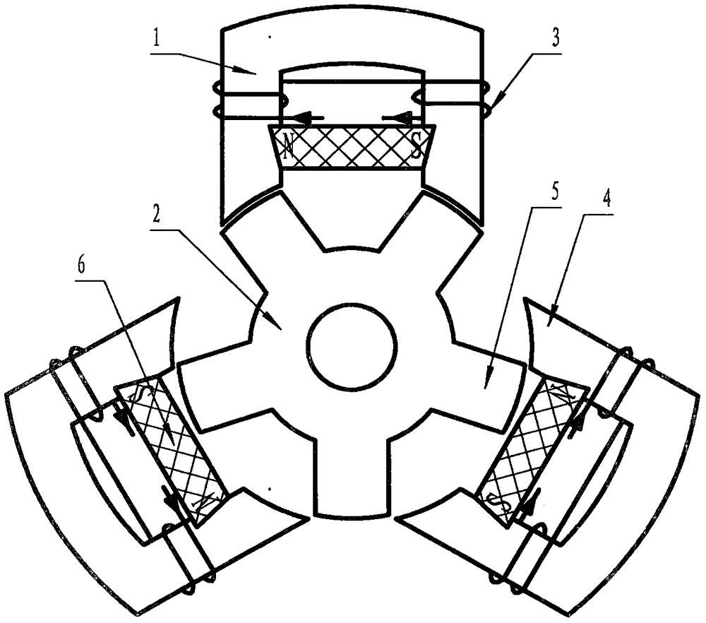
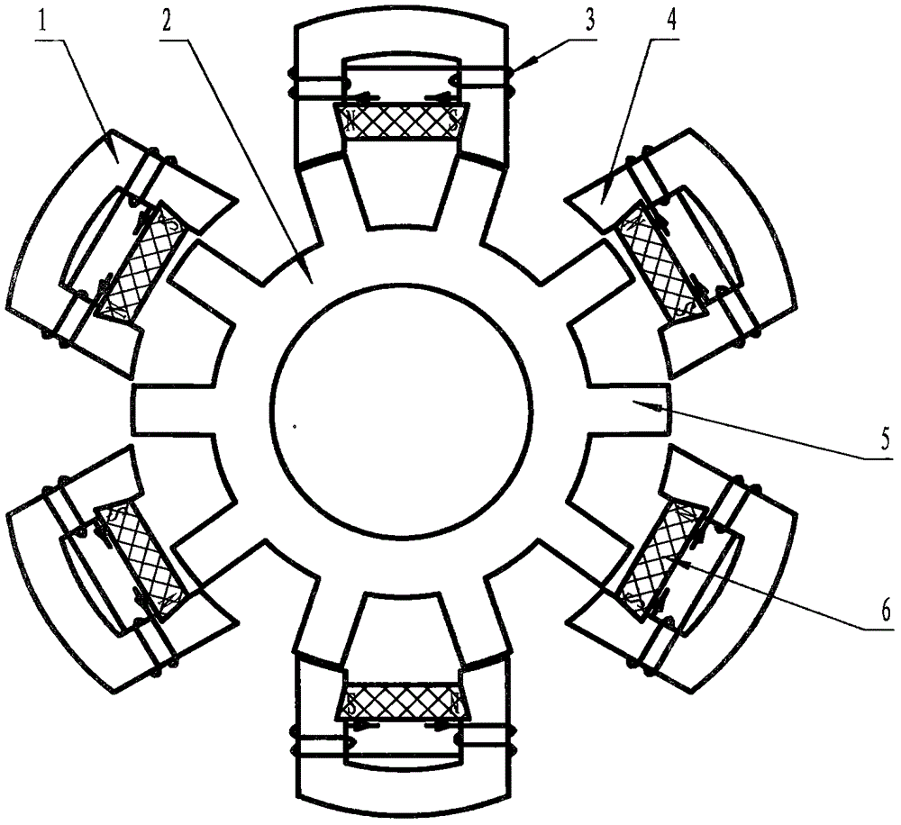
[0032] When the U-shaped stator permanent magnet switched reluctance motor provided by the present invention has three phases, the motor can be divided into a three-phase 6 / 5 structure and a three-phase 12 / 10 structure, and the working principle is the same.

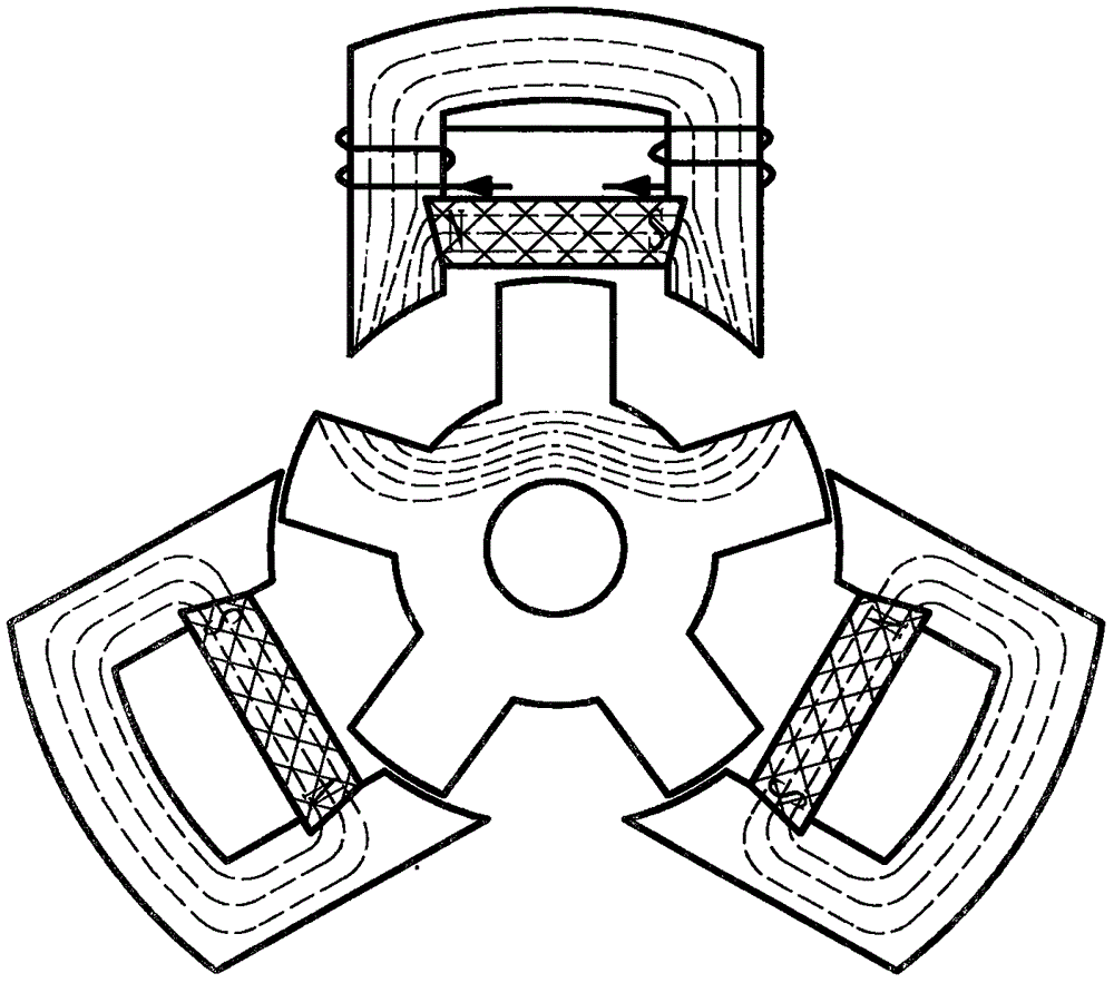
[0033] The cross-sectional structure of the U-shaped stator permanent magnet switched reluctance motor of the three-phase 6 / 5 structure of the present invention is as follows figure 1 As shown, it includes U-shaped stator block 1 , rotor 2 , field winding 3 and permanent magnet 6 . Three U-shaped stator blocks 1 are evenly distributed in the circumferential direction of the salient poles of the rotor 2. There is a permanent magnet installation slot 9 at the notch of each U-shaped stator block 1, and the permanent magnet 6 is placed on the permanent magnet of the U-shaped stator block 1. In the installation slot 9, the NS pole of the permanent magnet 6 is superimposed with the same polarity of the electromagnetic NS pole ...


PUM


Abstract

The invention belongs to the field of motors, and relates to a U-shaped stator permanent magnet switched reluctance motor. The U-shaped stator permanent magnet switched reluctance motor includes a rotor and a plurality of U-shaped stator blocks arranged on the circumference of the rotor, outer sides of rotor teeth of the rotor are outer arcs, inner sides of stator teeth of the U-shaped stator blocks are inner arcs, and air gaps are arranged between the outer arcs of the rotor teeth and the inner arcs of the stator teeth; the plurality of U-shaped stator blocks form a modular stator, a permanent magnet is arranged on an inner side wall of each U-shaped stator block, and superposition of like polarities occur in polarities of the permanent magnets and electromagnetic polarities generated by U-shaped stator block exciting windings. When the phase number of the motor is N, the number ratio of the stator teeth to the rotor teeth of the motor is 2N to (2N-1), for example, when the phase number of the motor is three, the motor is of a three-phase 6/5 structure or a three-phase 12/10 structure. The stator of the motor is the modular stator, modular production is facilitated, interphase magnetic paths are not coupled and completely isolated, and meanwhile, the motor has the advantages of high output, simple structure, easy maintenance, high fault-tolerance performance, convenient control and high reliability.

Description

Background technique: [0001] The stator and rotor of the traditional switched reluctance motor are salient pole structures. By sequentially energizing the stator excitation winding, the rotor poles interact with the stator poles to generate torque. Since there is neither permanent magnet nor winding on the rotor, the structure of the motor is simple and the reliability is high. But because neither the stator nor the rotor uses permanent magnets, in order to obtain greater output torque and power, it can only be achieved by increasing the excitation power, which increases the cost of the drive system and reduces the power density of the motor and torque density. [0002] In addition, in the traditional switched reluctance motor, when one of the adjacent phases is working, the other phases interfere with each other through the salient poles of the rotor, and the magnetically conductive stator yokes are connected to each other. The magnetically conductive magnetic path of the wo...

Claims


Application Information

Patent Timeline
Patent Type & Authority Applications(China)
IPC IPC(8): H02K16/00H02K29/00H02K21/00H02K1/24H02K1/14
Inventor 刘连龙
Owner 赵明珍
Why Eureka
Try Eureka