
positioning hinge

A hinge and positioning groove technology, applied in the hinge field, can solve the problems of positioning error, positioning angle deviation, and difficult to control the precision of positioning angle interval.

Active Publication Date: 2017-12-01
JARLLYTEC CO LTD
View PDF6 Cites 0 Cited by
  • Summary
  • Abstract
  • Description
  • Claims
  • Application Information

AI Technical Summary

Problems solved by technology

[0004] Although the cam structure of the aforementioned hinge can provide the positioning function when opening or contracting, but because the hinge is designed through miniaturization, the fixed and movable cams of the cam structure are limited in size, and are not suitable for multi-stage positioning. And if the distance between adjacent positioning angles is too small, it will often cause positioning errors.
Inquiring into the reason, it is difficult to control the precision when the distance between adjacent positioning angles is too small, and a little carelessness will cause positioning angle deviation. If precision manufacturing is used, it will inevitably lead to high manufacturing costs, which needs to be improved urgently.

Method used


Image

  • positioning hinge
  • positioning hinge
  • positioning hinge

Examples


Embodiment Construction

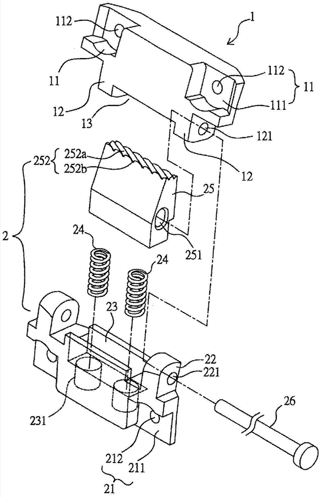
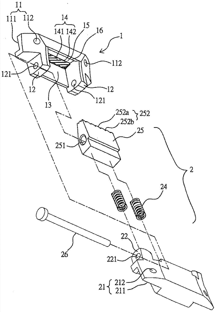
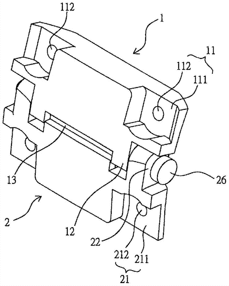
[0021] as 1 and image 3 As shown, basically, the positioning hinge of the present invention includes a fixed part 1 and a movable part 2 .

[0022] There is a first connection part 11 on the top of the fixing part 1, so as to be connected to the body 31 of a wearable electronic device 3 (please refer to Figure 4 ), a pair of first connecting grooves 111 are radially recessed on both sides of the first connecting portion 11, and each first connecting groove 111 is provided with at least one first connecting hole 112 in the radial direction, so that known connecting parts, such as screws, can pass through Behind the first connecting hole 112 is locked on the outer end of the body 31 of the wearable electronic device 3 . A pair of side walls 12 protrude from both sides of the lower side of the first connecting portion 11, and a pair of first shaft holes 121 are formed in the axial direction of the pair of side walls for the rear shaft 26 to pass through, and a further boundary...


PUM


Abstract

The invention provides a positioning hinge which comprises a fixed part and a movable part. By pulling the movable part, multiple oblique second arc convex teeth and tooth concaves on the top face of a clamping part pivoted on the movable part can be made to move between multiple oblique first arc convex teeth and tooth concaves in an accommodating groove of the fixed part and a positioning groove, and the second arc convex teeth and tooth concaves are made to be engaged with the first arc tooth concaves and convex teeth, or partially engaged with the first arc tooth concaves and convex teeth and partially accommodated in the positioning groove, or buckled in the positioning groove, so that the first positioning angle relation or the second positioning angle relation or the third positioning angle relation is formed respectively.

Description

technical field [0001] The invention relates to a hinge, especially a positioning hinge device with a positioning function. The positioning hinge is suitable for wearable electronic devices and has the requirement of fast wearing. Background technique [0002] Wearable electronic devices, such as smart watches and bracelets, are mostly presented in the form of watches or bracelets. On the one hand, the wearable electronic devices can display real-time information of smart phones, check the time, reply to messages and other functions. On the other hand, the functions It is a fitness monitoring function, which records the user's location information, heartbeat frequency, etc. Therefore, wearing convenience is also a goal pursued by wearable electronic devices, so as to avoid inconvenience in use caused by time-consuming wearing. Therefore, the related industry hopes to apply the miniaturized hinge to the above-mentioned wearable electronic device, so that the hinge can provid...

Claims


Application Information

Patent Timeline
Patent Type & Authority Patents(China)
IPC IPC(8): F16C11/10F16C11/12
Inventor 许有村高伟程
Owner JARLLYTEC CO LTD
Learn More