Handheld radio comprehensive tester

A comprehensive tester and radio technology, applied in transmitter monitoring, receiver monitoring, etc.

A comprehensive tester and radio technology, applied in transmitter monitoring, receiver monitoring, etc.

CN105281850AInactive Publication Date: 2016-01-27CHNEGDU CHIFFO ELECTRONICS INSTR

Image

  • Handheld radio comprehensive tester
  • Handheld radio comprehensive tester

Examples


Embodiment Construction

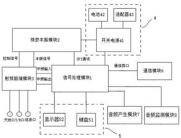
[0031] Below according to the appendix figure 1 , attached figure 2 The specific embodiments of the present invention are briefly described.

[0032] A handheld radio comprehensive tester, comprising a signal processing module 1, a radio frequency front-end module 3, a frequency-referenced local oscillator module 2, a power supply module 4 and an input and output module 5; the signal processing module 1 and the radio frequency front-end module 3, A frequency-referenced local oscillator module 2, a power supply module 4, and an input and output module 5 are connected; the power supply module 4 is also connected to the frequency-referenced local oscillator module 2, and the frequency-referenced local oscillator module 2 is connected to the radio frequency front-end module 3 connection; the radio frequency front-end module 3 is used to receive or send radio signals; the frequency-referenced local oscillator module 2 is used to provide a mixing signal for the radio frequency fr...


PUM


Abstract

The invention provides a handheld radio comprehensive tester comprising a signal processing module, a radio frequency front-end module, a frequency parameter local oscillator module, a power supply module and an input and output module. The signal processing module is connected with the radio frequency front-end module, the frequency parameter local oscillator module, the power supply module and the input and output module simultaneously. The power supply is also connected with the frequency parameter local oscillator module simultaneously. The frequency parameter local oscillator module is connected with the radio frequency front-end module. The radio frequency front-end module is used for receiving or transmitting radio signals. The frequency parameter local oscillator module is used for providing frequency mixing signals for the radio frequency front-end module. The signal processing module is used for controlling operation of each module and analyzing and processing the signals transmitted by the radio frequency front-end module. Integration of multiple measurement functions can be realized and measurement of multiple functions can be realized.

Description

technical field [0001] The invention relates to electronic measuring instruments, in particular to a hand-held radio comprehensive tester. Background technique [0002] At present, a single test is used for on-site test instruments of communication devices, and one instrument only measures a few functions, and cannot realize the measurement of multiple functions. Contents of the invention [0003] In order to solve the problem that multiple functions cannot be measured on the same instrument, the present invention provides a hand-held radio comprehensive tester. [0004] In order to solve the problems of the technologies described above, the present invention provides the following technical solutions: [0005] A hand-held radio comprehensive tester, comprising a signal processing module, a radio frequency front-end module, a frequency parameter local oscillator module, a power supply module and an input and output module; modules, input and output modules; the power mod...

Claims


Application Information

Patent Timeline
27 Jan 2016
Publication
CN105281850A
IPC
H04B17/15; H04B17/29
Inventors
何华章; 刘克农