Device for detecting air density in natural gas pipeline

A natural gas pipeline and gas density technology, which is applied in the direction of measuring devices, pipeline systems, gas/liquid distribution and storage, etc., can solve problems such as unfavorable popularization and application of multi-point real-time monitoring systems, high cost of detection methods, and complicated operations, etc., to achieve Effect of avoiding natural gas leakage, low cost, high accuracy and stability

Inactive Publication Date: 2016-04-06
XIAN TIANHENG MEASURING INSTR
View PDF4 Cites 0 Cited by
  • Summary
  • Abstract
  • Description
  • Claims
  • Application Information

AI Technical Summary

Problems solved by technology

However, the current detection method has high cost, large error and complex operation, which is not conducive to the popularization and application of multi-point real-time monitoring system

Method used


Image

  • Device for detecting air density in natural gas pipeline
  • Device for detecting air density in natural gas pipeline

Examples


Embodiment Construction

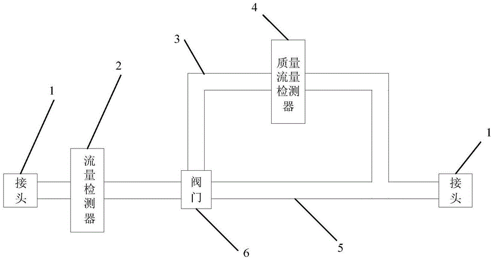
[0017] Such as figure 1 , 2 As shown, a device for detecting gas density in a natural gas pipeline includes: a joint 1, a flow detector 2, a straight pipe section 5, a valve 6, a detection pipe section 3, and a mass flow detector 4;

[0018] The joint 1 is arranged at both ends of the straight pipe section 5, and is used to connect the pipeline to be tested;

[0019] The flow detector 2 and the valve 6 are sequentially connected through the straight pipe section 5;

[0020] One end of the detection pipe section 3 is set at the connection between the valve 6 and the straight pipe section 5, and the other end communicates with the straight pipe section 5. When there is gas passing through the straight pipe section, the valve 6 can selectively let the gas flow in according to the signal sent by the flow detector 2. Detect pipe section 3 or subsequent straight pipe section 5;

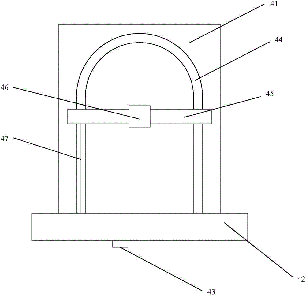
[0021] The mass flow detector 4 is arranged inside the detection pipe section 3 for detecting the gas...


PUM


Abstract

The invention discloses a device for detecting the air density in a natural gas pipeline. The device comprises connectors, a flow detector, a straight pipe section, a valve, a detection pipe section and a mass flow detector, wherein the connectors are arranged at the two ends of the straight pipe section and used for connecting the pipeline to be connected; the flow detector and the valve are connected in a communicated mode sequentially through the straight pipe section; one end of the detection pipe section is arranged in the connecting position of the valve and the straight pipe section, and the other end of the detection pipe section is communicated with the straight pipe section. When gas passes through the straight pipe section, the valve enables the gas to selectively flow into the detection pipe section or the subsequent straight pipe section according to the signals emitted by the flow detector. The mass flow detector is arranged inside the detection pipe section and used for detecting the gas passing through the detection pipe section. By means of the device, the technical problem that water is prone to being accumulated in the natural gas pipeline and causes corrosion is solved.

Description

technical field [0001] The invention relates to a natural gas pipeline network monitoring system, in particular to a device for detecting gas density in a natural gas pipeline. Background technique [0002] Although the natural gas has been dried before entering the transmission pipeline, due to the long transportation distance and many links, the external environment of the pipeline laying is complex, the liquid near the pipeline or the liquid produced by other links will seep into the pipeline, forming internal water, which will deteriorate Internal corrosion causes pipeline leakage, reduces structural strength, and seriously threatens the safety, integrity and economy of the entire gas transmission system. Therefore, in the natural gas pipeline network monitoring system, it is necessary to detect the gas density at all times to judge whether the gas in the pipeline is mixed with liquid vapor, avoid the generation of internal water, and eliminate the hidden danger of inter...

Claims


Application Information

Patent Timeline
Patent Type & Authority Applications(China)
IPC IPC(8): F17D5/02G01N9/00
Inventor 吴新潮
Owner XIAN TIANHENG MEASURING INSTR
Why Eureka
Try Eureka