
Dual mode operation led lights
A technology of LED lights and patterns, which can be used in the layout of electric light circuits, light sources, lighting devices, etc., and can solve problems such as electric shock danger and life-threatening installation personnel.
- Summary
- Abstract
- Description
- Claims
- Application Information
AI Technical Summary
Problems solved by technology
Method used
Image

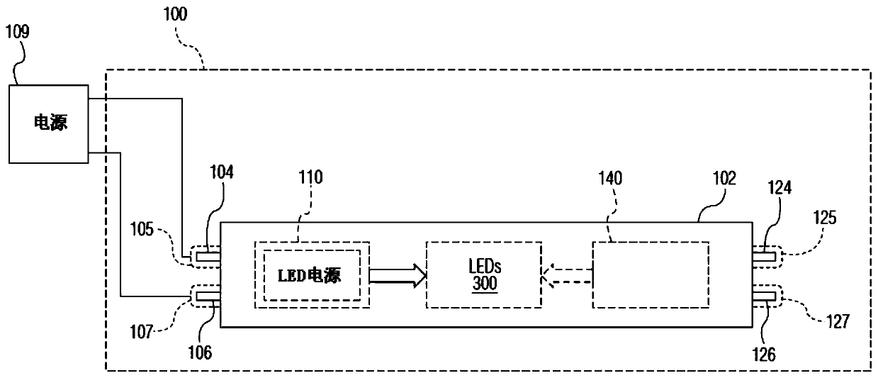
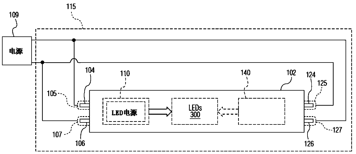
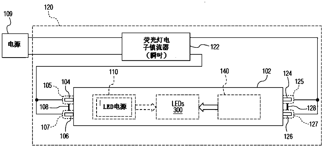
Examples
Embodiment 1-13
[0126] for Figure 16 All the embodiments 1-13 shown in, according to the table below, can realize the following first conduction control function:
[0127] Implementation of the first conduction control member 350
Functions of the first conduction control member 350
Capacitor 352
(1)–(4)
switch 354
(1)–(2) and (4)
Short circuit 358
(1)
[0128] Capacitor 352 may be referred to more broadly as capacitance, as is well known in the art. The broader term "capacitance" includes the use of multiple capacitors to achieve the required capacitance.
[0129] for Figure 16 All the embodiments 1-13 shown in, according to the following table, can realize the following second conduction control function:
[0130] Implementation of the second conduction control member 370
Function of the second conduction control member 370
Capacitor 374
(1)–(4)
switch 376
(1)–(2) and (4)
short circuit 372
(1) ...
Embodiment 5-10
[0136] Regarding embodiments 5-10, although it is more preferable to use a less expensive non-isolated first circuit 110, a more expensive isolated first circuit 110 may also be used.
[0137] refer to Figure 11 , Embodiment 11 implements the first and second conduction control members 350 and 370 as short circuits 358 and 372, respectively. Fluorescent lamp holder 115 ( figure 2 ), and by making the LED power supply behave as an isolated type in the first circuit 110, the following advantages can be achieved: the second circuit 140 does not interfere with the first circuit 110 regardless of the flickering interference or continuous interference discussed above.
[0138] Embodiment 12 uses an isolated LED power supply in the first circuit 110, and avoids the use of the fluorescent lamp holder 115 ( figure 2 ), to achieve the following advantage: no matter it is the flicker-type interference discussed above or the continuous-type interference, the second circuit 140 does n...
PUM
 Abstract
Description
Claims
Application Information