LED lamp with dual mode operation

A technology of LED lamps and LED circuits, which is applied to the layout of lamp circuits, light sources, lighting devices, etc., and can solve problems such as electric shock hazards and threats to the lives of installers

Active Publication Date: 2016-04-27
ENERGY FOCUS INC
View PDF8 Cites 6 Cited by
  • Summary
  • Abstract
  • Description
  • Claims
  • Application Information

AI Technical Summary

Problems solved by technology

Therefore, there will be a potential electric shock hazard, that is, in the pro

Method used


Image

  • LED lamp with dual mode operation
  • LED lamp with dual mode operation
  • LED lamp with dual mode operation

Examples


Embodiment 1-13

[0126] for Figure 16 All the embodiments 1-13 shown in, according to the table below, can realize the following first conduction control function:

[0127] Implementation of the first conduction control member 350

Functions of the first conduction control member 350

Capacitor 352

(1)–(4)

switch 354

(1)–(2) and (4)

Short circuit 358

(1)

[0128] Capacitor 352 may be referred to more broadly as capacitance, as is well known in the art. The broader term "capacitance" includes the use of multiple capacitors to achieve the required capacitance.

[0129] for Figure 16 All the embodiments 1-13 shown in, according to the following table, can realize the following second conduction control function:

[0130] Implementation of the second conduction control member 370

Function of the second conduction control member 370

Capacitor 374

(1)–(4)

switch 376

(1)–(2) and (4)

short circuit 372

...

Embodiment 5-10

[0136] Regarding embodiments 5-10, although it is more preferable to use a less expensive non-isolated first circuit 110, a more expensive isolated first circuit 110 may also be used.

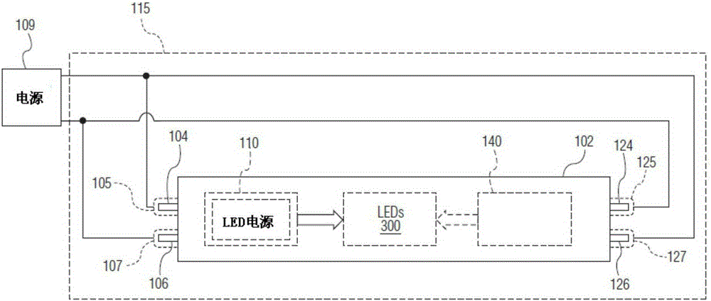
[0137] refer to Figure 11 , Embodiment 11 implements the first and second conduction control members 350 and 370 as short circuits 358 and 372, respectively. Fluorescent lamp holder 115 ( figure 2 ), and by allowing the LED power supply to behave as an isolated type in the first circuit 110, the following advantages can be achieved: the second circuit 140 does not interfere with the first circuit 110 regardless of the flickering interference or continuous interference discussed above.

[0138] Embodiment 12 uses an isolated LED power supply in the first circuit 110, and avoids the use of the fluorescent lamp holder 115 ( figure 2 ), to achieve the following advantage: no matter it is the flicker-type interference discussed above or the continuous-type interference, the second circuit 140 d...


PUM


Abstract

An LED lamp has dual modes of operation from fluorescent lamp fixtures. A first circuit powers at least one LED in a first mode of operation when first and second power connector pins at a first end of the lamp are inserted into power receptacles of the fixture that are directly connected to power mains. A second circuit powers at least one LED in a second mode of operation when the second power connector pin at the first end of the lamp and a third power connector pin at a second end of the lamp are inserted into power receptacles of a fixture powered from an electronic ballast. First and second conduction control means permit the second circuit to power at least one LED during the second mode of operation.

Description

technical field [0001] The LED lamp involved in the present invention adopts dual-mode operation, which can be connected to the transmission power through the fluorescent lamp frame or provided with electric power through the electronic ballast connected with the lamp frame. Background technique [0002] A traditional slim LED (Light Emitting Diode) light can be retrofitted into an existing fluorescent light fixture with its wiring reconfigured to provide mains power directly to the LED light. The "modified" LED lights usually deliver power from a pair of power pins at one end of the light, and a pair of wiring pins at the other end of the light. They are not used to deliver power, but to provide mechanical support for the light. The above-mentioned design of power supply through the power pin at one end of the lamp helps to reduce the potential life threat of the installer due to electric shock from the main current during the installation process of the lamp. [0003] The...

Claims


Application Information

Patent Timeline
IPC IPC(8): H05B37/02
Inventor 约翰·M·达文波特大卫·比纳耶利米·埃尔曼
Owner ENERGY FOCUS INC
Why Eureka
Try Eureka