Mining borehole radar advanced water detecting forecasting device and forecasting method

A drilling radar and mining technology, applied in the field of geophysical radar wave detection, can solve the problems of large influence of observation results, increased forecast cost, poor multi-solution ability, etc. Accurate, reliable, time- and cost-saving effects

Active Publication Date: 2016-05-18
WUHAN CONOURISH COALMINE SAFETY TECH +1
View PDF5 Cites 9 Cited by
  • Summary
  • Abstract
  • Description
  • Claims
  • Application Information

AI Technical Summary

Problems solved by technology

[0005] The above geophysical methods are all drilling detection methods after tunnels, roadways, working faces or boreholes are drilled. Various metal facilities such as steel support, bolt support, and conveyor belt support have a great influence on the observation results of the three-pole method and the mine transient electromagnetic method. The parameter is single, only one parameter of resistivity is used, and the ability to eliminate multiple solutions is poor, resulting in multiple solutions
If the above-mentioned multiple methods are used in combination, the forecasting cost of advanced forecasting will be greatly increased; and the drilling detection method performed after the hole is drilled is unable to detect because the coal seam is soft and the drilling hole often collapses.
The seismic wave method mainly solves the problem of the interface of the geological structure, but cannot explain the water-richness of the structure; the borehole electrical method and the borehole electromagnetic method cannot judge and explain the size and distance of the water-bearing body

Method used


Image

  • Mining borehole radar advanced water detecting forecasting device and forecasting method
  • Mining borehole radar advanced water detecting forecasting device and forecasting method
  • Mining borehole radar advanced water detecting forecasting device and forecasting method

Examples


Embodiment Construction

[0028] Below in conjunction with accompanying drawing and specific embodiment the present invention is described in further detail:

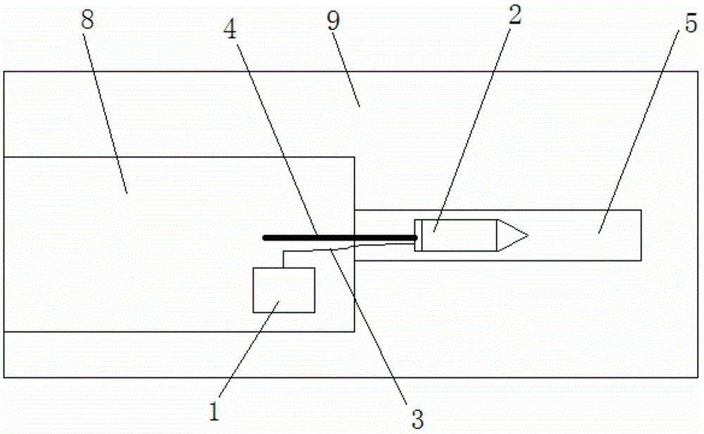
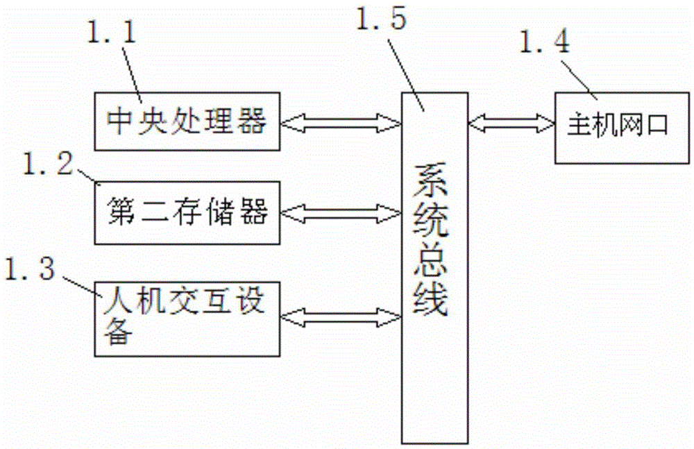
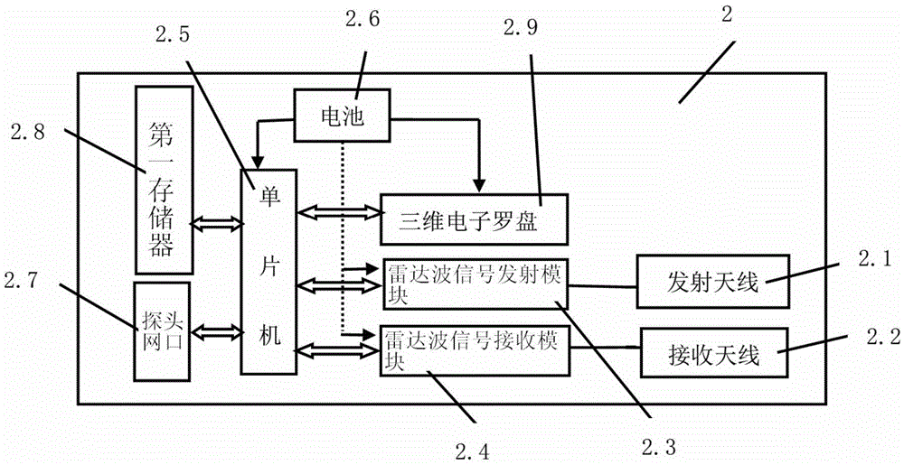
[0029] Such as Figure 1~4 The mine borehole radar advanced water detection and forecasting device shown in the figure includes an on-site host 1 (set in the roadway 9), a probe 2, a network cable 3, a push rod 4, a transmitting antenna 2.1 and a receiving antenna 2.2 set in the probe 2 , radar wave signal transmitting module 2.3, radar wave signal receiving module 2.4, single-chip microcomputer 2.5, battery 2.6, probe network port 2.7, first memory 2.8 and three-dimensional electronic compass 2.9, wherein, the signal output terminal of described radar wave signal transmitting module 2.3 Connect with the signal input end of transmitting antenna 2.1, the signal input end of radar wave signal receiving module 2.4 is connected with the signal output end of receiving antenna 2.2; The communication end of described radar wave signal transmitting modu...


PUM


Abstract

The invention discloses a mining borehole radar advanced water detecting forecasting device. A signal output end of a radar wave signal transmitting module is connected with a signal input end of a transmitting antenna, and a signal input end of a radar wave signal receiving module is connected with a signal output end of a receiving antenna. The communication end of the radar wave signal transmitting module and the communication end of the radar wave signal receiving module are respectively connected with a signal transmitting communication end and a signal receiving communication end of a single-chip microcomputer. A communication end of a memory and a communication end of a three-dimensional electronic compass are respectively connected with the data storage communication end and the compass data communication end of the single-chip microcomputer. The data communication end of the single-chip microcomputer is connected with a data communication end of an on-site host by a probe network interface and a network cable. The eutrophic water, the water diversion channel, and other harmful geological bodies around the drilled hole can be detected, and the fine and effective detection forecast can be carried out.

Description

technical field [0001] The invention relates to the technical field of applied geophysical radar wave detection, in particular to a mining borehole radar advance water detection and forecasting device and method. Background technique [0002] Coal mine advanced water exploration is mainly to detect whether there are harmful geological structures or rich water bodies and water-conducting channels in front of the tunnel, roadway excavation direction and working face by direct or indirect methods at the head of the tunnel, and provide detailed information for safe tunneling. detection data. [0003] At present, the direct method used for advanced detection of coal mines is the drilling method, and the indirect method is the geophysical method. Although the drilling results of the drilling method are relatively reliable, the construction period is long and the cost is high, which has a great impact on the normal production of tunnels and roadways. [0004] At present, the geoph...

Claims


Application Information

Patent Timeline
Patent Type & Authority Applications(China)
IPC IPC(8): G01S13/88
CPCG01S13/885
Inventor 武强刘鎏曾一凡陶凤娟刘春生
Owner WUHAN CONOURISH COALMINE SAFETY TECH
Why Eureka
Try Eureka