A digital holographic phantom imaging system using a single-pixel barrel detector and its working method
A technology of phantom imaging and digital holography, which is applied in the direction of instruments, etc., can solve the problem of difficulty in producing large-scale high-resolution area array devices for digital holographic recording, complex data processing operations, and low target surface size and resolution of area array photodetectors. And other issues
- Summary
- Abstract
- Description
- Claims
- Application Information
AI Technical Summary
Problems solved by technology
Method used
Image
Examples
Embodiment 1
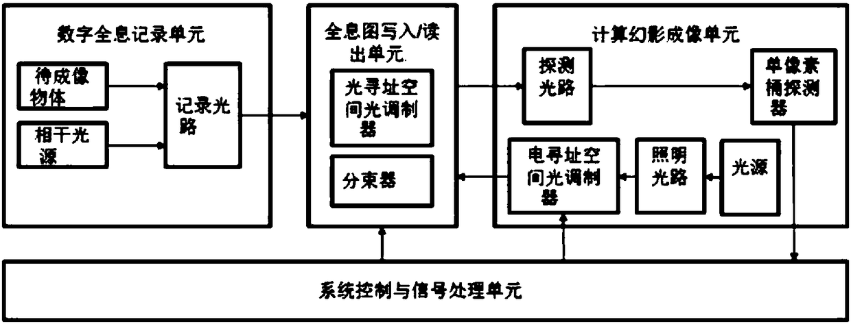
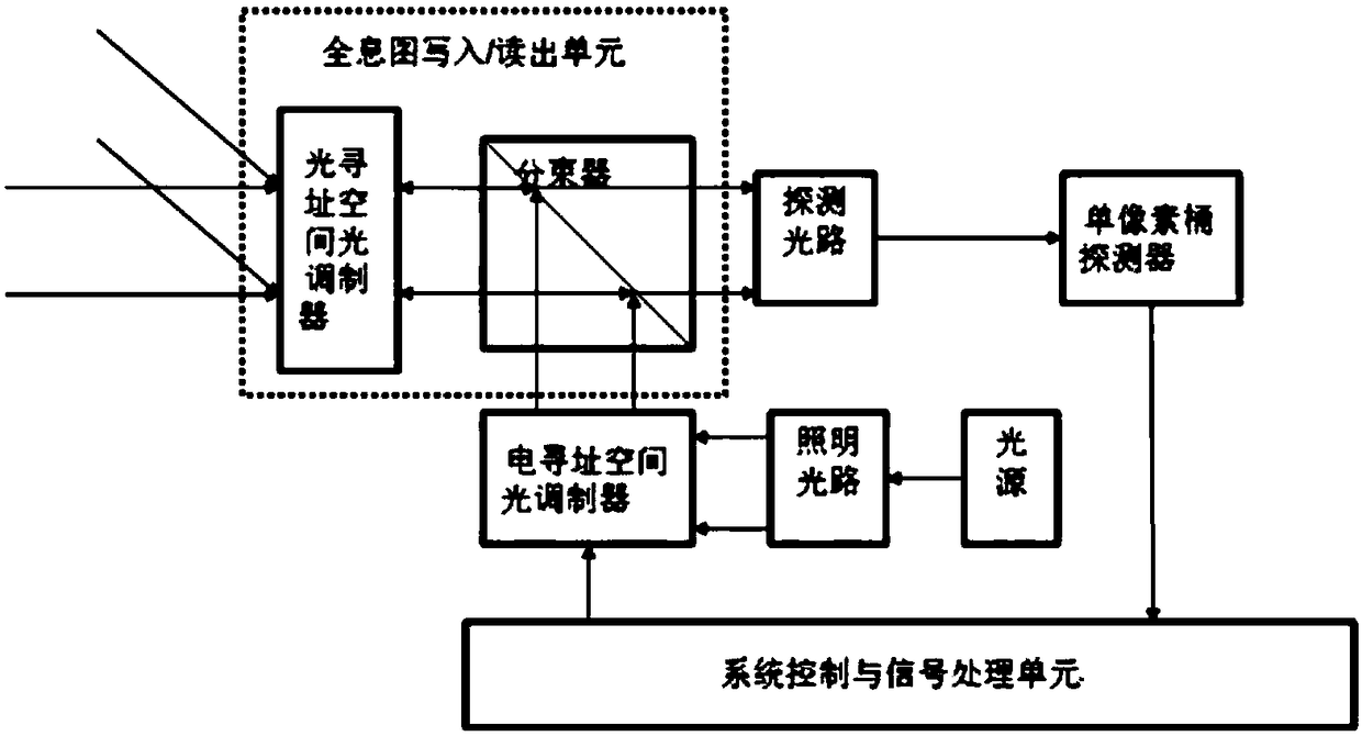
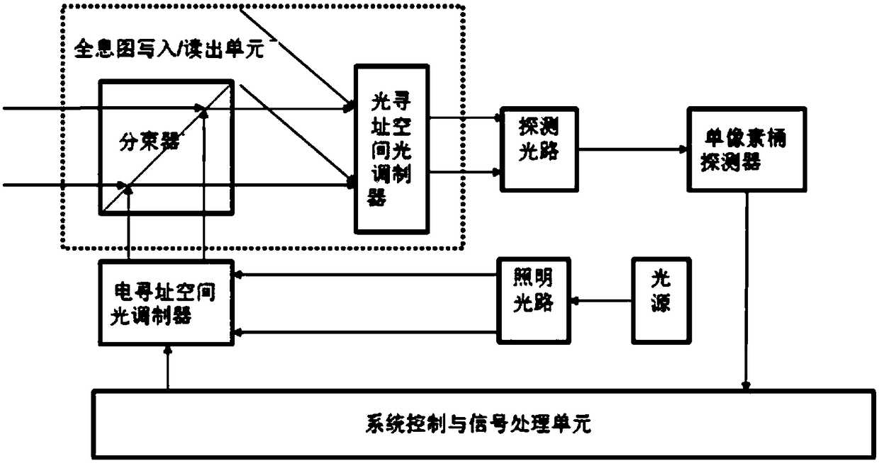
[0085] A digital holographic phantom imaging system using a single-pixel barrel detector, comprising a digital holographic recording unit, a hologram writing / reading unit, a computational phantom imaging unit, and a system control and signal processing unit, the digital holographic recording unit, the The hologram writing / reading unit and the computing phantom imaging unit are sequentially connected;
[0086] The digital holographic recording unit includes an object to be imaged, a coherent light source and a recording optical path, the object to be imaged and the coherent light source are respectively connected to the recording optical path, and the recording optical path is connected to the hologram writing / reading unit; The object to be imaged includes a transmission object or a reflection / scattering object, includes an amplitude type object or a phase type object or an amplitude / phase composite type object. The coherent light sources are all kinds of light sources with cer...
Embodiment 2
[0097] The working method of the above-mentioned digital holographic phantom imaging system, the specific steps include:
[0098] A. Execute steps (1) and (2) N times to complete N detections
[0099] (1) Generation and writing of holograms
[0100] a. The coherent light source emits coherent light waves, and the coherent light waves pass through the object to be imaged and the recording optical path to obtain object light waves O(x, y) and reference light waves R(x, y);
[0101] b, the object light wave O (x, y) and the reference light wave R (x, y) overlap and interfere on the writing surface of the optical addressable spatial light modulator, forming an intensity distribution of I H The interference pattern of (x, y) is shown in formula (I):
[0102] I H (x, y) = |O(x, y)| 2 +|R(x,y)| 2 +O * (x,y)R(x,y)+O(x,y)R * (x, y) (I)
[0103] In formula (I), O * (x, y) and R * (x, y) are the complex conjugates of O(x, y) and R(x, y), respectively.
[0104] c. Based on the ...
PUM
 Abstract
Description
Claims
Application Information
 - R&D
- Intellectual Property
- Life Sciences
- Materials
- Tech Scout
- Unparalleled Data Quality
- Higher Quality Content
- 60% Fewer Hallucinations
Browse by: Latest US Patents, China's latest patents, Technical Efficacy Thesaurus, Application Domain, Technology Topic, Popular Technical Reports.
© 2025 PatSnap. All rights reserved.Legal|Privacy policy|Modern Slavery Act Transparency Statement|Sitemap|About US| Contact US: help@patsnap.com


