Digital holography ghost imaging system by adopting single-pixel or bucket detector and working method thereof

A phantom imaging and digital holography technology, which is applied in the direction of instruments, can solve the limitations of digital holographic imaging resolution, field of view and its application fields, low target size and resolution of area array photodetectors, and complex calculations for data processing And other issues

Inactive Publication Date: 2016-06-15
SHANDONG UNIV
View PDF14 Cites 18 Cited by
  • Summary
  • Abstract
  • Description
  • Claims
  • Application Information

AI Technical Summary

Problems solved by technology

[0003] In recent years, with the development of computers, especially high-resolution area array photodetectors, digital holography technology and its applications have received more and more attention, but there are still two problems in practical applications: (1) area array The target surface size and resolution of photodetectors are far lower than optical holographic recording media, which makes digital holography very limited in terms of imaging resolution, field of view and application fields; (2) in certain wavebands (such as infrared, Terahertz, etc.), due to the limitations of materials and processes, it is still difficult to produce large-size, high-resolution area array devices for digital holographic recording
[0013] Both of the above two patents use the phase iteration method to obtain the three-dimensional information of the object. It is necessary to add a pseudo-random phase to the pulsed light. After multiple measurements, complex calculations are required for data processing.

Method used


Image

  • Digital holography ghost imaging system by adopting single-pixel or bucket detector and working method thereof
  • Digital holography ghost imaging system by adopting single-pixel or bucket detector and working method thereof
  • Digital holography ghost imaging system by adopting single-pixel or bucket detector and working method thereof

Examples


Embodiment 1

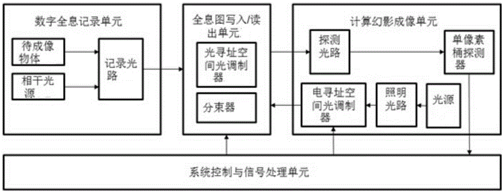
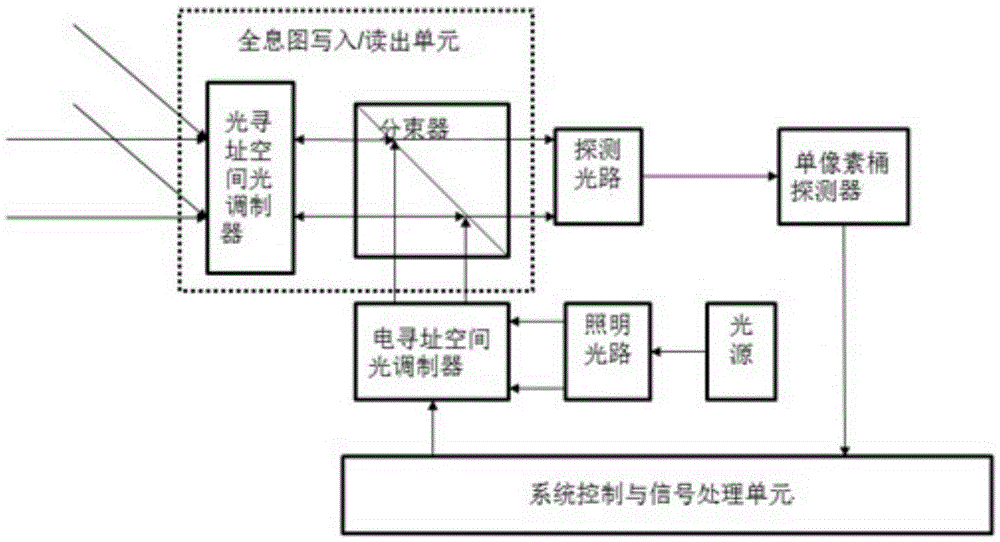
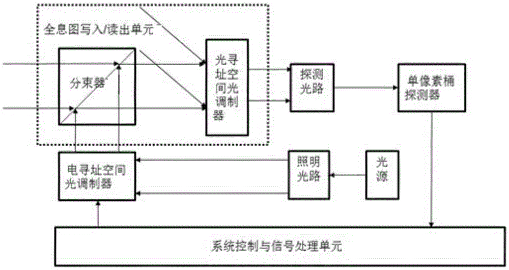
[0085] A digital holographic phantom imaging system using a single-pixel barrel detector includes a digital holographic recording unit, a hologram writing / reading unit, a computational phantom imaging unit, and a system control and signal processing unit. The digital holographic recording unit, The hologram writing / reading unit and the computational phantom imaging unit are connected in sequence;

[0086] The digital holographic recording unit includes an object to be imaged, a coherent light source and a recording optical path, the object to be imaged and the coherent light source are respectively connected to the recording optical path, and the recording optical path is connected to the hologram writing / reading unit; The object to be imaged includes a transmission object or a reflection / scattering object, including an amplitude type object or a phase type object or an amplitude / phase composite type object. The coherent light sources are various types of light sources with certa...

Embodiment 2

[0097] The specific steps of the above-mentioned digital holographic phantom imaging system working method include:

[0098] A. Perform steps (1) and (2) N times to complete N detections

[0099] (1) Generation and writing of hologram

[0100] a. The coherent light source emits coherent light waves, and the coherent light waves obtain the object light wave O(x, y) and the reference light wave R(x, y) through the object to be imaged and the recording light path;

[0101] b. The object light wave O (x, y) and the reference light wave R (x, y) overlap and interfere on the writing surface of the optical addressing spatial light modulator, forming an intensity distribution of I H The interference pattern of (x,y) is shown in formula (I):

[0102] I H (x,y)=|O(x,y)| 2 +|R(x,y)| 2 +O * (x,y)R(x,y)+O(x,y)R * (x,y)(I)

[0103] In formula (Ⅰ), O * (x, y) and R * (x, y) are the complex conjugates of O(x, y) and R(x, y), respectively.

[0104] c. Based on the electro-optical or magneto-optical physic...


PUM


Abstract

The invention relates to a digital holography ghost imaging system by adopting a single-pixel or bucket detector and a working method thereof. The system comprises a digital holography recording unit, a hologram writing / reading unit, a computational ghost imaging unit and a system control and signal processing unit, wherein the digital holography recording unit generates a hologram of a target object and the hologram serves as writing light to be written in the hologram writing / reading unit; and the computational ghost imaging unit generates structured light which can be dynamically refreshed and carries reference matrix encoding information, and the structured light serves as reading light to read the hologram, and the hologram is received by the single-pixel or bucket detector. The method of the invention combines the ghost imaging and the digital holography, and the problems that the size of the target surface of a plane array photoelectric detector and the resolution are insufficient and plane array photoelectric detectors of certain wave bands are hard to make as a result of limitations such as the material and the technology in the digital holography technology applications can be solved.

Description

Technical field [0001] The invention relates to a digital holographic phantom imaging system using a single-pixel barrel detector and a working method thereof, belonging to the technical field of photoelectric imaging, display and detection. Background technique [0002] Holography is invented in 1948 by Gabor, a British-born Hungarian scientist. It is based on interference and diffraction between coherent light waves (here "light waves" can be electromagnetic waves of other wavelengths), and can record and reproduce the amplitude and phase information of light waves. The technology has wide applications in the fields of information recording and storage, imaging and display, interferometry and detection, information security and anti-counterfeiting identification. Since the 1960s, the development of laser light sources has provided a good coherent light source for the research and application of holography. Optical holography has entered a period of vigorous development, and dif...

Claims


Application Information

Patent Timeline
Patent Type & Authority Applications(China)
IPC IPC(8): G03H1/08G03H1/22
CPCG03H1/0866G03H1/2294
Inventor 王玉荣龙涛孟祥锋江山李永富刘兆军殷永凯
Owner SHANDONG UNIV
Why Eureka
Try Eureka